Ball screw type ship swinging and vibration reducing supporting device

A technology of ball screw type and vibration damping support, which is applied in the direction of transmission device, spring/shock absorber, vibration suppression adjustment, etc., can solve the problems of engineering practical value limitation, low operation reliability, high cost, etc., and improve the use of Longer service life, improved anti-rolling effect, and reduced maintenance cost

Active Publication Date: 2017-05-31
JIANGSU UNIV OF SCI & TECH
View PDF5 Cites 9 Cited by
  • Summary
  • Abstract
  • Description
  • Claims
  • Application Information

AI Technical Summary

Problems solved by technology

However, this device involves not only the hydraulic system, but also the electronic control system, so the cost is relatively expensive, the structure is relatively complicated, and the operation reliability is low, so the practical value of the project is limited

Method used


Image

  • Ball screw type ship swinging and vibration reducing supporting device
  • Ball screw type ship swinging and vibration reducing supporting device
  • Ball screw type ship swinging and vibration reducing supporting device

Examples


Embodiment 1

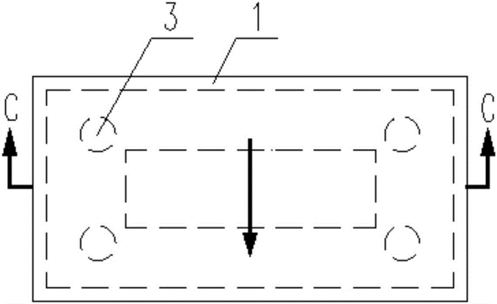
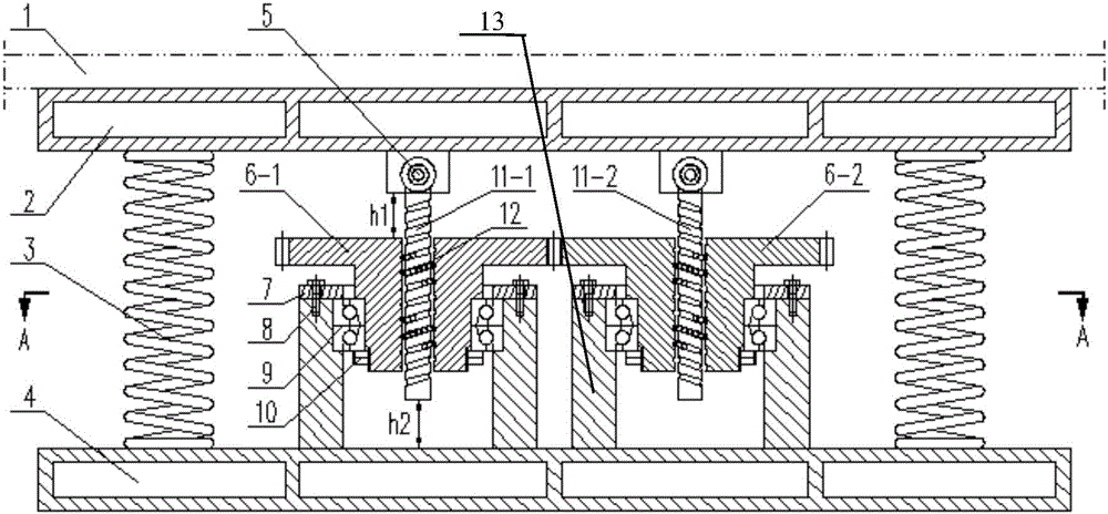
[0028] Such as Figure 1-2 As shown, a ball screw type marine anti-vibration support device includes an upper support frame 2, a spring 3, a lower support frame 4, a ball screw assembly and a flywheel assembly.

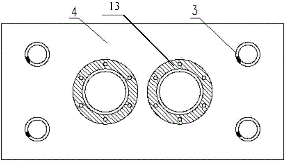
[0029] Such as figure 2 As shown, the upper support frame 2 is connected to the mechanical equipment 1, and the lower support frame 4 is fixed to the hull. In this embodiment, the upper support frame 2 and the lower support frame 4 are two identical hollow rectangular plates. The four corners of the rectangular plate are symmetrically provided with springs 3 , one end of the spring 3 is connected to the upper supporting frame 2 , and the other end is connected to the lower supporting frame 4 .

[0030] The lower surface of the upper supporting frame 2 is provided with a rotating support, and the ball screw assembly is rotatably mounted on the rotating supporting frame through the pin shaft 5, and the leading screws 11-1, 11-2 can rotate relative to the upper suppor...

Embodiment 2

[0040] In this embodiment, the thread directions of the two screw screws 11-1, 11-2 of the ball screw assembly are the same, and the flywheels 6-1, 6-2 are connected to each other through the synchronous gear belt 14, so that the flywheels 6-1, 6 The steering of -2 is in the same direction. In this embodiment, the other structural features are the same as those in Embodiment 1 except that the screw thread direction of the lead screw 11-1, 11-2 and the way of cooperation of the flywheel 6-1, 6-2 are different from Embodiment 1.

[0041] In this embodiment, when the mechanical equipment 1 swings counterclockwise relative to the forward direction 13 of the ship, the upper supporting frame 4 swings counterclockwise, driving the right screw 11 to move upward and the left screw 11 to move downward. The left lead screw 11 that moves downward drives the left flywheel 6 to rotate counterclockwise, the left flywheel 6 that rotates counterclockwise drives the right flywheel 6 to rotate c...


PUM


Abstract

The invention discloses a ball screw type ship swinging and vibration reducing supporting device. The ball screw type ship swinging and vibration reducing supporting device comprises an upper bearing frame, springs, a lower bearing frame, ball screw assemblies arranged in pair and the like. Vibration generated through operation of ship mechanical equipment is transmitted to the upper bearing frame, and vibration is reduced by the springs to be transmitted to a ship body; the mechanical equipment is caused to swing together through low-frequency swinging of the ship body in waves, the overall torsion rigidity of a base is adjusted through the ball screw assemblies and a flywheel assembly, accordingly, swinging of the mechanical equipment is synchronous with swinging of the ship but not amplified, the overall torsion rigidity of a bottom frame is improved, and the swinging movement of the mechanical equipment is reduced. According to the ball screw type ship swinging and vibration reducing supporting device, modular design, manufacturing and installing are adopted, the structure is simple, cost is low, and the swinging and vibration reducing effect is good.

Description

technical field [0001] The invention relates to a support device for marine mechanical equipment, in particular to a ball screw type marine anti-rolling and vibration-reducing support device, which belongs to the technical field of ship vibration reduction equipment. Background technique [0002] Marine machinery equipment can be divided into power machinery equipment and non-power machinery equipment. For power machinery equipment, such as the main engine, it is necessary to actively isolate its vibration to reduce the impact of the vibration generated by its work on the surrounding environment. For non-power machinery equipment, such as marine The operating table needs to be passively isolated from vibration to reduce the influence of the surrounding environment on it, so as to ensure the reliability of its work. [0003] In addition, during the sailing process of the ship, due to the action of wind and waves, the hull will also sway, and the moment generated by the hull s...

Claims


Application Information

Patent Timeline
Patent Type & Authority Applications(China)
IPC IPC(8): F16F15/02F16F15/067F16F15/30F16H25/22
CPCF16F15/02F16F15/067F16F15/30F16H25/2204F16H2025/249F16F7/1022F16F2232/06
Inventor 温华兵郭俊华刘悦李阳
Owner JIANGSU UNIV OF SCI & TECH
Why Eureka
Try Eureka