Sintering furnace capable of reducing heat loss

A technology of heat loss and sintering furnace, applied in the field of sintering furnace, can solve the problems of heat loss, reduce the sintering rate, etc., and achieve the effect of reducing floor space, reducing heat loss, and saving plant resources

Inactive Publication Date: 2017-05-31
CHONGQING HEHAI CARBON PROD
View PDF6 Cites 4 Cited by
  • Summary
  • Abstract
  • Description
  • Claims
  • Application Information

AI Technical Summary

Problems solved by technology

[0005] The present invention intends to provide a sintering furnace capable of reducing heat loss, which can

Method used


Image

  • Sintering furnace capable of reducing heat loss
  • Sintering furnace capable of reducing heat loss

Examples


Embodiment Construction

[0019] The present invention will be described in further detail below by means of specific embodiments:

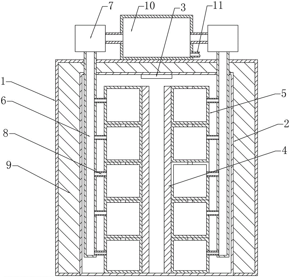
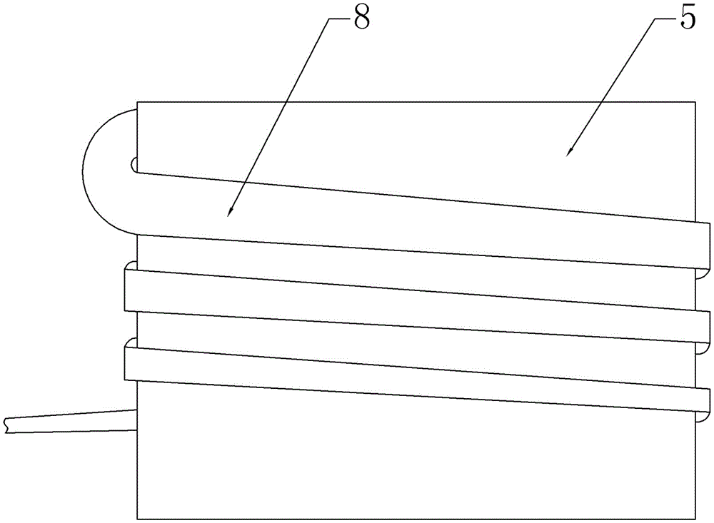
[0020] The reference signs in the drawings of the description include: furnace body 1, furnace gall 2, thermocouple 3, heating rod 4, crucible 5, main pipeline 6, smoking device 7, smoke exhaust pipe 8, heat preservation material 9, water storage tank 10 , Sewage pipe 11.

[0021] This example figure 1 with figure 2 As shown, the sintering furnace capable of reducing heat loss includes a furnace body 1 and a furnace body 2 , the furnace body 2 is located in the furnace body 1 , and the lower end of the furnace body 2 is fixedly connected to the furnace body 1 . The cavity between the furnace gall 2 and the furnace body 1 is filled with an insulating material 9, and the insulating material 9 is ceramic fiber. The upper end of the furnace body 1 is fixedly connected with a water storage tank 10, and the water storage tank 10 is provided with a sewage pipe 11, and the se...


PUM


Abstract

The invention relates to the technical field of carbon brush processing, in particular to a sintering furnace capable of reducing heat loss. The sintering furnace comprises a furnace body and a furnace liner located in the furnace body. A thermocouple, a heating bar and a plurality of crucibles are arranged in the furnace liner. The multiple crucibles are stacked vertically and provided with smoke discharge holes. A water storage tank and a smoke exhausting device are arranged at the upper end of the furnace body. A sewage discharge pipe communicates with the water storage tank. A vertical main is further arranged in the furnace liner. The upper end of the main penetrates through the furnace liner and the furnace body to be located outside the furnace body and is connected with the water storage tank through the smoke exhausting device. Smoke discharge pipes communicate with the crucibles and are around the side walls of the crucibles. One ends of the smoke discharge pipes are connected with the crucibles through the smoke discharge holes, and the other ends of the smoke discharge pipes communicate with the main. The sintering furnace can solve the problem that an existing device easily causes a large amount of heat loss, and accordingly the sintering rate is reduced.

Description

technical field [0001] The invention relates to the technical field of carbon brush processing, in particular to a sintering furnace capable of reducing heat loss. Background technique [0002] A carbon brush is a device that transmits energy or signals between the fixed part and the rotating part of a motor, generator or other rotating machinery. After the carbon brush is pressed and formed, it needs to be sintered, the purpose of which is to improve the mechanical strength of the product, reduce the resistance and fix its geometry. Since the raw materials of the carbon brush include resin and pitch, a large amount of dense smoke will be generated during the high-temperature sintering process. The main components of the dense smoke are particles such as resin and pitch high-temperature treatment volatiles and sulfides. This kind of dense smoke is likely to pollute the surface of the carbon brush and affect product quality. [0003] In order to solve the above problems, th...

Claims


Application Information

Patent Timeline
IPC IPC(8): F27B14/06F27B14/08F27D17/00
CPCF27B14/06F27B14/08F27B2014/0843F27D17/004F27D17/008F27M2001/04F27M2003/04
Inventor 曹双全
Owner CHONGQING HEHAI CARBON PROD
Why Eureka
Try Eureka