Non-contact type bearing ring inside diameter measurement device

A bearing ring, measuring device technology, applied in the direction of measuring devices, optical devices, instruments, etc., can solve the problems of the influence of thin-walled bearing parts, the large error of instrument indication value, the surface scratches of parts, etc., to ensure the surface integrity , The adjustment is convenient and reliable, and the effect of improving the measurement accuracy

Inactive Publication Date: 2017-05-31
HENAN UNIV OF SCI & TECH
View PDF7 Cites 14 Cited by
  • Summary
  • Abstract
  • Description
  • Claims
  • Application Information

AI Technical Summary

Problems solved by technology

[0003] (1) The cemented carbide probe used in bearing special instruments is easy to cause scratches on the surface of bearing parts during the measurement process. Ordinary bearings are acceptable, but any tiny flaws in high-precision bearings will affect product quality, which is absolutely not allowed of
[0004] (2) For some thin-walled bearings, manual measurement on a special instrument, the external force of the hand has a great impact on the measurement results, which is far from meeting the measurement requirements of the bearing accuracy
[0005] (3) The indication error of special instruments is relatively large, which cannot meet the measurement requirements of some precision bearings
[0006] (4) There are many deficiencies in the use of other high-precision measuring instruments: ① contact measurement is mostly a two-point measurement method for determining the diameter, and only one diameter can be measured at a time, which cannot meet the requirements of the bearing inspection standard for parameters such as average diameter and diameter variation , and the time is long and the eff

Method used


Image

  • Non-contact type bearing ring inside diameter measurement device
  • Non-contact type bearing ring inside diameter measurement device
  • Non-contact type bearing ring inside diameter measurement device

Examples


Embodiment Construction

[0027] Embodiments of the present invention will be further described below in conjunction with the accompanying drawings.

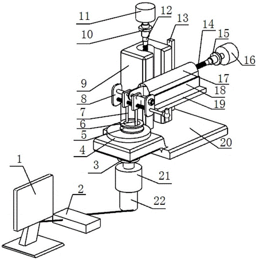
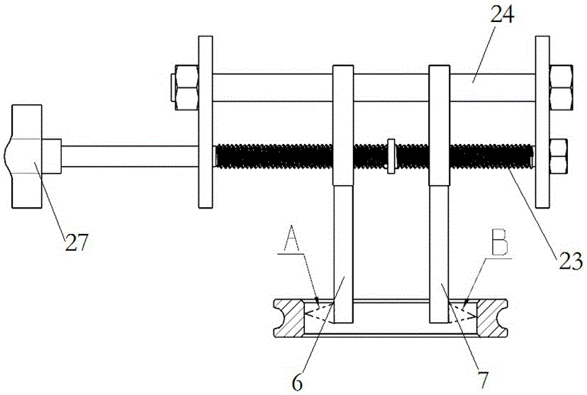
[0028] The specific embodiment of the non-contact bearing ring inner diameter measuring device provided by the present invention, as Figure 1 to Figure 3 As shown, the measuring device in this embodiment includes a base 20, on which a sensor mounting frame 8 is installed through a sliding table adjustment mechanism, and the sensor mounting frame 8 is provided with two laser displacement sensors distributed radially along the bearing ring. In this embodiment, the spacing distribution direction of the two laser displacement sensors is specifically defined as the left and right directions, and the two laser displacement sensors include a first sensor 6 and a second sensor 7 distributed at a left and right interval, and the two laser displacement sensors have respectively a A probe that, when inserted into a bearing ring, faces outwards towards the inner su...


PUM


Abstract

The invention relates to a non-contact type bearing ring inside diameter measurement device, which comprises a sensor mounting frame and a rotation drive mechanism; the sensor mounting frame is provided with two laser displacement sensors which are distributed at intervals in the radial direction of a bearing ring and are provided with measurement heads used for facing the inner surface of the bearing ring outwards when the laser displacement sensors are inserted into the bearing ring respectively; and the rotation drive mechanism is used for realizing relative rotation between the bearing ring to be measured and each laser displacement sensor. According to the non-contact type bearing ring inside diameter measurement device, by adopting the non-contact type laser displacement sensors to carry out measurement, a part to be measured can be effectively prevented from being scratched, and the surface integrity of the part is guaranteed; relative rotation between the bearing ring to be measured and each laser displacement sensor is realized by utilizing the rotation drive mechanism, so that the inside diameters and inside diameter change amounts of the bearing rings at different angle positions can be measured, and the measurement accuracy is effectively improved.

Description

technical field [0001] The invention relates to a device for measuring the inner diameter of a non-contact bearing ring. Background technique [0002] Bearing is a kind of high-precision mechanical parts. Its size and geometry are the main factors of bearing accuracy level. Measurement is a necessary means to judge size and geometry. At present, in the bearing processing process and its finished product measurement, most of the bearing special instruments are used to realize the measurement. Bearing-specific instruments have the advantages of simple operation, easy learning, low price, durability, and high measurement efficiency, but there are also certain limitations, as follows: [0003] (1) The cemented carbide probe used in the bearing special instrument is easy to scratch the surface of the bearing parts during the measurement process. Ordinary bearings are acceptable, but any tiny flaws in high-precision bearings will affect product quality, which is absolutely not al...

Claims


Application Information

Patent Timeline
IPC IPC(8): G01B11/12G05D3/12
Inventor 李济顺薛玉君马喜强马俊余永健李伦司东宏马伟杨芳隋新刘春阳韩红彪
Owner HENAN UNIV OF SCI & TECH
Why Eureka
Try Eureka