
Double-arc high-feed annular milling cutter and its preparation process and detection method

A circular milling cutter and double-arc technology, which is applied in the control of workpiece feed movement, milling cutter, milling machine equipment, etc., can solve the problems of residual step surface, limited feed rate, large cutting force, etc., and achieve reduction Cutting force, good cutting performance and tool life, and the effect of improving grinding efficiency

Inactive Publication Date: 2019-07-23
HARBIN UNIV OF SCI & TECH
View PDF9 Cites 0 Cited by
  • Summary
  • Abstract
  • Description
  • Claims
  • Application Information

AI Technical Summary

Problems solved by technology

In order to achieve better cutting performance, many studies have focused on the optimization of milling parameters and processes, but these studies are bound to be limited by tool structure, machine tool torque and precision, and it is difficult to further improve processing speed and efficiency.
When using a ring milling cutter to process a mold with a concave surface, it is easy to have a residual step surface; due to the participation of the rounded cutting edge in the cutting process to a certain extent, the feed rate is limited and the cutting force is large

Method used


Image

  • Double-arc high-feed annular milling cutter and its preparation process and detection method
  • Double-arc high-feed annular milling cutter and its preparation process and detection method
  • Double-arc high-feed annular milling cutter and its preparation process and detection method

Examples


Embodiment 1

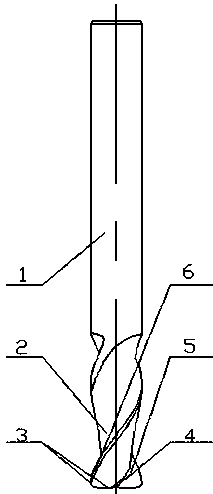
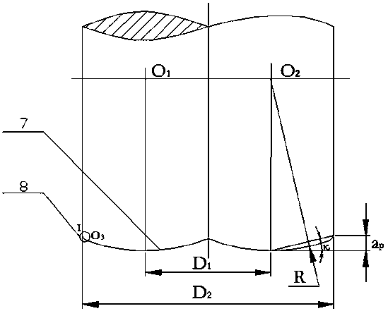
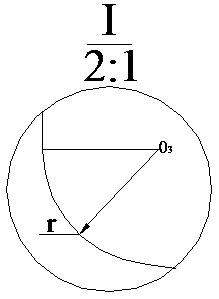
[0030] A double-arc high-feed annular milling cutter, which consists of: an annular milling cutter shank 1, the front end of the annular milling cutter shank is sequentially connected with a spiral sipe 2, a double-arc high-feed cutting edge 3, and an end tooth The chip pocket 4 is connected, and the double-arc high-feed cutting edge has a double-arc high-feed cutting edge rake face 5 and a double-arc high-feed cutting edge flank 6, and the double-arc The high-feed cutting edge includes a main arc cutting edge 7 and a sub-arc cutting edge 8 .

Embodiment 2

[0032] According to the double-arc high-feed annular milling cutter described in embodiment 1, the described knife handle is a cylindrical knife handle with strong rigidity and a diameter of 20mm, which is used for semi-finishing, and the material is hard alloy. Milling hardened die steel.

Embodiment 3

[0034] According to the double-arc high-feed ring milling cutter described in Embodiment 1, the double-arc high-feed cutting edge has certain advantages in terms of milling characteristics. By controlling the radian of the main arc cutting edge and the sub-arc cutting edge to control the cutting main deflection angle, the cutting angle of milling is small, thin chips are formed during the cutting process, and the feed rate is increased, thereby improving the metal removal rate. When the main arc cutting edge has a concave arc cutting edge structure to participate in the cutting of the concave curved surface, the remaining step area is reduced to zero, ensuring the uniformity of the cutting residue height in semi-finishing.


PUM


Abstract

The present invention relates to a preparation process and a monitor method of a double-arc large feed ring mill cutter. Currently, ring mill cutter having curved surface high adaptability is widely used in aerospace, automotive and other mold curved surface semi-finishing field, but in order to achieve better cutting performance, improvement of milling efficiency by breakthroughs in the aspects of cutting feed, cutting forces and the like has certain difficulty, on the other hand, grinding process affects processing efficiency, tool life and surface integrity of a workpiece, meanwhile the method for effectively verifying the accuracy of the grinding is worth of considering. The double-arc large feed ring mill cutter comprises a ring mill cutter handle (1), the front end of the ring mill cutter handle is successively connected with a spiral cutter groove (2), a double-arc large feed cutting edge (3), and an end tooth chip pocket (4), the double-arc large feed cutting edge comprises a main-arc cutting edge (7) and a sub-arc cutting edge (8). The double-arc large feed ring mill cutter is used for milling die steel, at the same time, a reference opinion for the preparation process and the monitor method of the mill cutter is provided.

Description

technical field [0001] The invention relates to a double-arc high-feed annular milling cutter, and specifically relates to a preparation process and a detection method of the annular milling cutter. Background technique [0002] At present, the ring milling cutter has high adaptability to connect the bottom edge and the peripheral edge to participate in the cutting and processing of curved surfaces through the rounded cutting edge, and the step distance of the ring milling cutter relative to the ball end milling cutter is larger in the case of equal residual height processing , reduced processing time, improved processing efficiency and other advantages, it is widely used in the semi-finishing fields of mold surfaces such as aviation, aerospace, and automobiles. In order to achieve better cutting performance, many studies have focused on the optimization of milling parameters and processes, but these studies are bound to be limited by tool structure, machine tool torque and ...

Claims


Application Information

Patent Timeline
Patent Type & Authority Patents(China)
IPC IPC(8): B23C5/10B24B3/06B24B49/12
CPCB23C5/1081B24B3/06B24B49/12
Inventor 陈涛王昌红李素燕王广越
Owner HARBIN UNIV OF SCI & TECH
Learn More