Laser ultrasonic detection method and system for temperature field in homogeneous material component

An internal temperature, laser ultrasonic technology, applied in thermometers, thermometers with physical/chemical changes, measuring devices, etc., can solve the problems affecting the temperature field distribution, affecting the accuracy and life of the sensor, large measurement errors, etc., to achieve anti-interference ability. The effect of strong, fast real-time response and high measurement accuracy

Active Publication Date: 2017-05-31
CHINA SPECIAL EQUIP INSPECTION & RES INST
View PDF5 Cites 8 Cited by
  • Summary
  • Abstract
  • Description
  • Claims
  • Application Information

AI Technical Summary

Problems solved by technology

However, when the above method measures the temperature of an object, there are many problems: (1) due to the need to wait for thermal equilibrium, the real-time response rate is relatively slow, and there is a certain delay; It directly affects the distribution of the temperature field inside the object, resulting in a large measurement error; (3) In the case of a very harsh temperature measurement environment, due to the need for a certain period of time for heat balance, the high temperature resistance, high pressure resistance and corrosion resistance of the temperature measurement sensor The performance requirements of materials such as high-performance materials greatly increase the difficulty and cost of sensor manufacturing, and when the temperature is too low or too high for an instant, it is easy to affect the accuracy and life of the sensor; (4) only the local temperature of the contact position can be measured , it is impossible to obtain the temperature field distributed along the object structure direction (such as axial, radial or thickness direction)

Method used


Image

  • Laser ultrasonic detection method and system for temperature field in homogeneous material component
  • Laser ultrasonic detection method and system for temperature field in homogeneous material component
  • Laser ultrasonic detection method and system for temperature field in homogeneous material component

Examples


Embodiment Construction

[0049] The present invention will be further described below in conjunction with the accompanying drawings and specific embodiments.

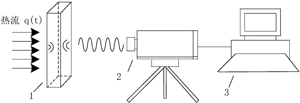
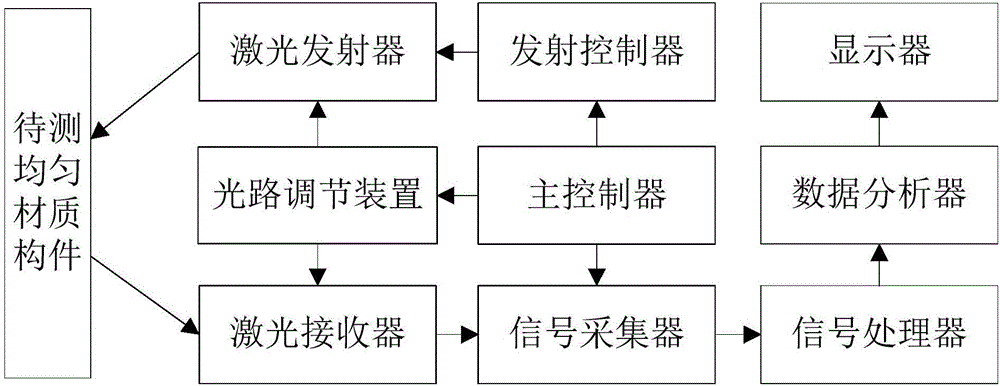
[0050] figure 1 It is a schematic diagram of the principle of the laser ultrasonic detection method. The entire laser ultrasonic temperature measurement system is composed of a laser ultrasonic device (2) and a computer (3). The laser ultrasonic device (2) integrates a laser transmitter, a laser receiver, and an optical path adjustment device. , launch controller, signal collector, main controller and signal processor, the computer (3) is mainly composed of data analyzer and display, and the system is composed of figure 2 shown. When detecting the internal temperature of a heated uniform material component (1), first activate the emission controller through the main controller inside the laser ultrasonic device (2), so that the emission controller controls the laser to emit laser light, and the laser light passes through the optical path adju...


PUM


Abstract

The invention relates to a laser ultrasonic detection method and system for temperature field in a homogeneous material component. The detection method comprises the steps that (1) the relationship between ultrasonic sound velocity and temperature in a homogeneous material is determined based on a calibration sample; (2) the thickness L of the homogeneous material component to be detected and the temperature T of the cold end are determined; (3) the ultrasonic transit time ttof in the homogeneous material component to be detected is acquired through laser ultrasonic measurement; (4) an ultrasonic temperature field is used to reconstruct a mechanism to acquire the internal temperature field distribution of the homogeneous material component to be detected. The detection method and system carry out fast, accurate, non-contact and high precision measurement on the internal temperature field of an object, can adapt to a harsh environment of high temperature, high pressure and strong corrosivity, and meet the needs of many complicated working conditions.

Description

technical field [0001] The invention relates to the technical field of non-contact detection of an internal temperature field of an object, in particular to a laser ultrasonic detection method and system for an internal temperature field of a uniform material component. Background technique [0002] For the measurement of the internal temperature of the object, the contact temperature measurement method is generally used, that is, the temperature sensor is in full contact with the object, and the heat balance between the two is achieved through heat exchange, thereby measuring the temperature value of the contact part of the object. However, when the above method measures the temperature of an object, there are many problems: (1) due to the need to wait for thermal equilibrium, the real-time response rate is relatively slow, and there is a certain delay; It directly affects the distribution of the temperature field inside the object, resulting in a large measurement error; (...

Claims


Application Information

Patent Timeline
Patent Type & Authority Applications(China)
IPC IPC(8): G01K11/22
CPCG01K11/22
Inventor 胡斌施超
Owner CHINA SPECIAL EQUIP INSPECTION & RES INST
Why Eureka
Try Eureka