
a constant temperature bath

A constant temperature tank and tank body technology, applied in thermometers, thermometer testing/calibration, instruments, etc., can solve the problems of small temperature adjustment range, unusable constant temperature tank, and undiscovered constant temperature tank, etc., to achieve compact overall layout, convenient debugging and maintenance , flexible installation and removal effect

Active Publication Date: 2019-04-05
BEIJING CHANGCHENG INST OF METROLOGY & MEASUREMENT AVIATION IND CORP OF CHINA
View PDF4 Cites 0 Cited by
  • Summary
  • Abstract
  • Description
  • Claims
  • Application Information

AI Technical Summary

Problems solved by technology

At present, the common thermostatic bath used in the high-precision temperature maintenance device has only one kind of temperature-regulating medium, and the temperature-regulating range is small.
In addition, the heat preservation part and the temperature regulation part of the common constant temperature tank are usually set in the same closed device, which can only be used under static conditions.
In some specific occasions, such as in the acceleration-temperature compound calibration equipment, it is required that the equipment can adjust the temperature and maintain a constant temperature while performing corresponding rotations under different accelerations. At this time, this type of common constant temperature bath cannot be used.
Have not found the relevant embodiment or published document of the constant temperature bath that can be used in this kind of scene at present

Method used


Image

  • a constant temperature bath
  • a constant temperature bath
  • a constant temperature bath

Examples


Embodiment Construction

[0027] The present invention will be further described below in conjunction with the accompanying drawings.

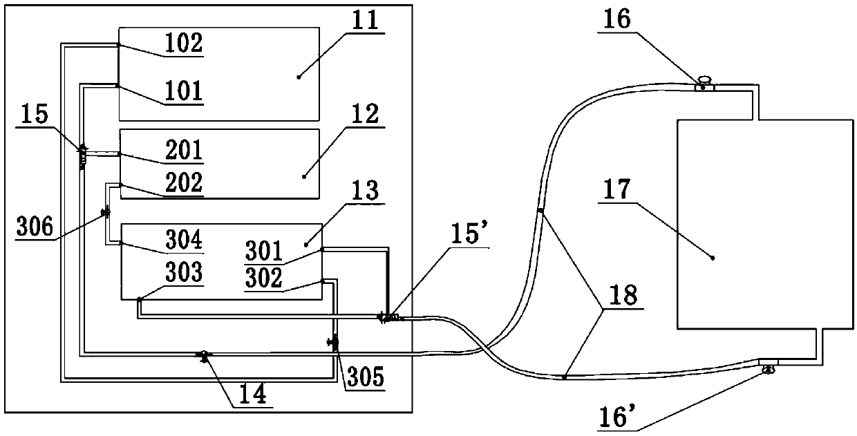
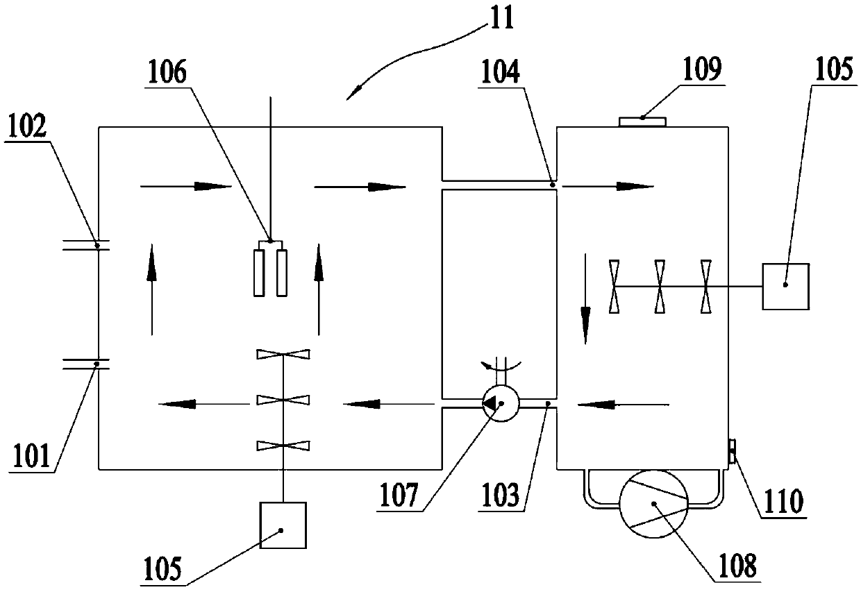
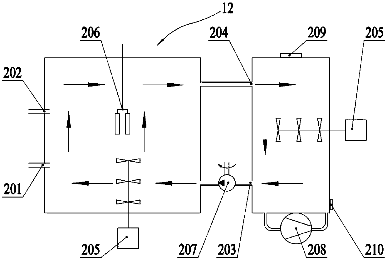
[0028] figure 1It is a schematic diagram of the overall structure of the first embodiment of the constant temperature bath. The constant temperature tank includes: the first medium constant temperature tank body 11, which is used to heat or cool the first medium contained in it; the second medium constant temperature tank body 12, which is used to heat or cool the first medium contained in it; Two kinds of media; liquid return tank 13, used to contain the first medium and the second medium returned after heat exchange; circulation pump 14, whose function is to provide flow for the first medium and the second medium power; two solenoid valves 15, 15' are used to control the one-way flow of medium; two heat exchange joints 16, 16' are used to control the on-off of heat exchange; heat exchanger 17 is used to provide heat exchange places , to make the target reach the se...


PUM


Abstract

The invention discloses a constant temperature bath. The constant temperature bath is used as a temperature regulating and maintaining device, and particularly suitable for an acceleration-temperature compound calibration device. The constant temperature bath comprises a first medium constant temperature bath body (11), a second medium constant temperature bath body (12), a liquid returning tank (13), a circulating pump (14), a solenoid valve (15, 15'), a heat exchange connector (16, 16'), a heat exchanger (17) and a pipeline (18) connected with each component. After the heat conduction medium is heated or cooled by the first medium constant temperature bath body (11) or the second medium constant temperature bath body (12), the heat conduction medium is flowed into the heat exchanger (17), where the calibration device is positioned, by the pipeline (18) through the circulating pump (14), the solenoid valve (15) and the heat exchange connector (16), and the heat conduction medium is returned to the liquid returning tank (13) through the heat exchange connector (16') and the solenoid valve (15'), finally the heat conduction medium is respectively flowed into the first medium constant temperature bath body (11) or the second medium constant temperature bath body (12) through a first medium liquid returning tank circulating pump (305) or a second medium liquid returning tank circulating pump (306).

Description

technical field [0001] The invention relates to a constant temperature tank, in particular to a dual constant temperature tank suitable for acceleration-temperature compound calibration equipment, and belongs to the technical field of inertial device compound measurement calibration. Background technique [0002] The constant temperature bath can provide a high-precision constant temperature field source. Specifically, the target temperature is generally maintained at the set temperature by adjusting the temperature of the medium in the tank. The constant temperature bath can be used in fine chemical industry, biological engineering, medicine and food, scientific experiment, metallurgy, petroleum, agriculture and other fields. At present, the common thermostatic tank used in high-precision temperature maintenance devices has only one kind of temperature-regulating medium, and the temperature-regulating range is small. In addition, the heat preservation part and the temperat...

Claims


Application Information

Patent Timeline
IPC IPC(8): G01K15/00B01L7/00
CPCB01L7/00G01K15/00
Inventor 董雪明何懿才
Owner BEIJING CHANGCHENG INST OF METROLOGY & MEASUREMENT AVIATION IND CORP OF CHINA
Learn More