Large-dynamic range calibration method for optical coherent domain polarimeter

A large dynamic range, optical coherence technology, applied in the direction of optical instrument testing, testing optical performance, testing optical fiber/optical waveguide equipment, etc., can solve the problems that the calibration range needs to be improved and limited

Active Publication Date: 2017-05-31
HARBIN ENG UNIV
View PDF12 Cites 14 Cited by
  • Summary
  • Abstract
  • Description
  • Claims
  • Application Information

AI Technical Summary

Problems solved by technology

However, it is also limited by the method used, and the calibration range needs to be improved
[0012] Calibration of test instruments is an essential step in scientific measurement. With the improvement of test accuracy, when ordinary methods cannot be calibrated, a device and method that can verify the accuracy of high-precision systems is needed. The accuracy of the system is getting higher and higher, and the existing calibration devices and methods are gradually no longer applicable, which requires a wider range of calibration methods, so that the current and future higher-precision coherent domain polarization test systems are based on evidence. can be relied on, which is of great significance for coherent domain testing

Method used


Image

  • Large-dynamic range calibration method for optical coherent domain polarimeter
  • Large-dynamic range calibration method for optical coherent domain polarimeter
  • Large-dynamic range calibration method for optical coherent domain polarimeter

Examples


Embodiment Construction

[0063] The present invention will be further described below with examples in conjunction with the accompanying drawings.

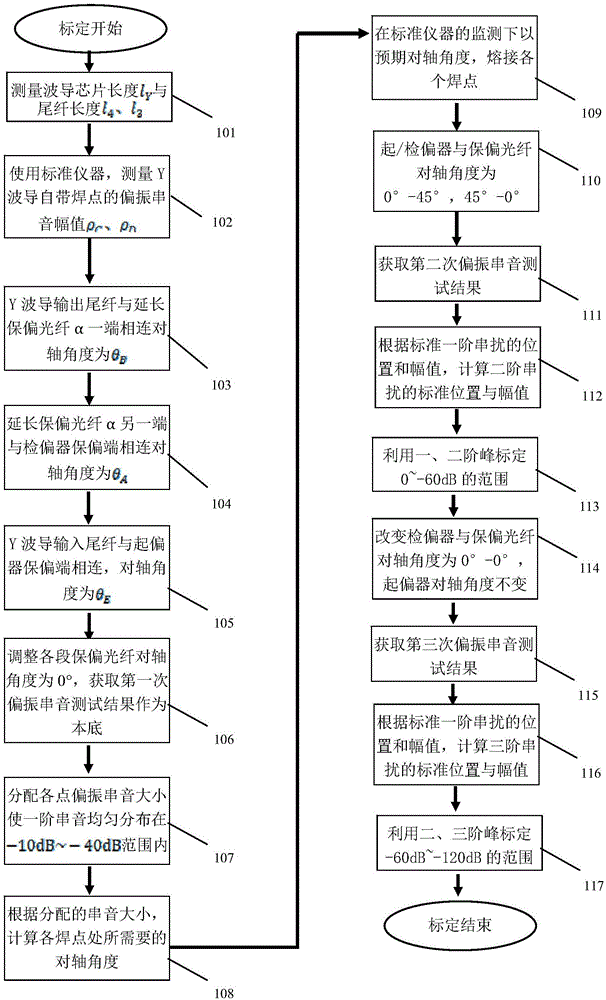
[0064] combine image 3 , the method for calibrating a large dynamic range optical coherence domain polarimeter of the present invention comprises the following steps:

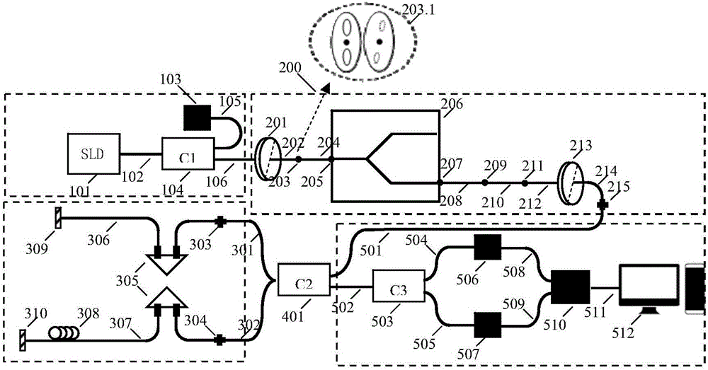
[0065] (101) measure the length l of the input polarization-maintaining pigtail 204 of the Y waveguide 4 , the length l of the output polarization maintaining pigtail 207 3 , the length l of the Y waveguide 206 chip Y .

[0066] (102) Use a standard instrument (such as an extinction ratio tester) to measure the polarization crosstalk value ρ of the waveguide's own output solder joint 207 C , Polarized crosstalk size ρ with input pad 205 D .

[0067] (103) Use a section of length l 2 The extended polarization-maintaining fiber 210 of the Y-waveguide is connected to the input polarization-maintaining pigtail 204 or the output polarization-maintaining pigtail 208 to introduce addition...


PUM


Abstract

The present invention provides a large-dynamic range calibration method for an optical coherent domain polarimeter. According to the method, interference peaks formed by polarized crosstalk at solder joints in an OCDP (Optical Coherence Domain Polarimetry) system are adopted as a transfer carrier; the scale of a standard is increased through higher-order crosstalk of which the peak value is lower, wherein the higher-order crosstalk is formed by one-order polarized crosstalk verified by a standard instrument; the standard is transferred to a system to be tested; and the peak values of one-order, two-order and third-order polarized crosstalk among the solder joints are evenly distributed in a range of 0 to -120dB through an opposite-axial angle between polarization maintaining optical fibers at the solder joints, and therefore, on-line calibration of the optical coherent domain polarization system is realized. With the method adopted, the calibration limits of a traditional method are broken through, and the online calibration of a system of which the dynamic range exceeds 100dB is realized. The method has the advantage of simple structure, easiness in implementation and high calibration precision.

Description

technical field [0001] The invention relates to an optical fiber measurement method, in particular to a calibration method of the high-order crosstalk calibration system itself using an optical coherence domain polarimeter. Background technique [0002] Polarization optical devices are an important part of high-precision optical measurement and sensing systems. At present, the performance testing and evaluation methods and devices of optical devices are backward, which seriously hinders the development of high-precision optical measurement and sensing systems. For example, the chip extinction ratio of lithium niobate integrated waveguide modulator (commonly known as Y waveguide), the core device of high-precision fiber optic gyroscope, has reached more than 80dB; The rate is around 50dB (according to the definition of energy, it is 10 5 ), the highest resolution is the Model 4810 polarization extinction ratio developed by dBm Optics of the United States, and the measurement...

Claims


Application Information

Patent Timeline
Patent Type & Authority Applications(China)
IPC IPC(8): G01M11/02
CPCG01M11/331G01M11/337G01M11/35
Inventor 杨军杨喆张浩亮彭峰苑勇贵苑立波
Owner HARBIN ENG UNIV
Why Eureka
Try Eureka