Pitch gyratory compactor

A technology of compactor and asphalt, which is applied in the field of auxiliary tooling for road material detection, can solve problems such as difficult braking and damage to the drive motor of the turntable, and achieves the effects of convenient power transmission, low energy loss, and improved detection efficiency

Active Publication Date: 2017-05-31
昆山市交通工程集团有限公司 +1
View PDF6 Cites 2 Cited by
  • Summary
  • Abstract
  • Description
  • Claims
  • Application Information

AI Technical Summary

Problems solved by technology

[0006] This gyratory compactor improves the control accuracy of the gyratory compactor by setting a braking mechanism, but when the gyratory tester is stopped, the drive motor will continue to rotate under the action of inertia to drive the turntable to rotate, and braking is difficult. When the brake mechanism acts on the turntable, it will cause damage to the turntable, brake mechanism and drive motor at the same time

Method used


Image

  • Pitch gyratory compactor
  • Pitch gyratory compactor
  • Pitch gyratory compactor

Examples


Embodiment 1

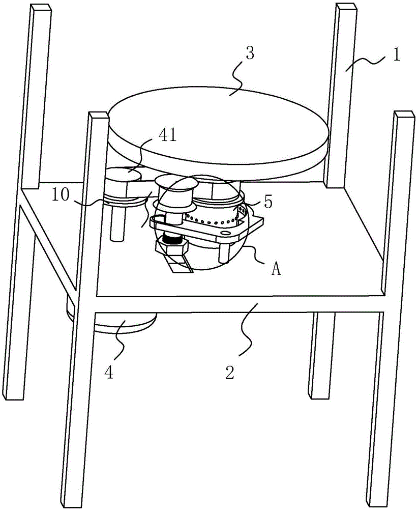
[0041] Embodiment one: a kind of asphalt rotary compactor, such as figure 1 As shown, the frame 1 is fixedly connected with a bottom plate 2, and the bottom plate 2 is rotatably connected with a rotating roller 5, and the end of the rotating roller 5 is sleeved with a turntable 3, and the bottom plate 2 is also fixedly connected with a driving motor 4, and the driving motor 4 passes Bolts are fixed on the lower surface of the base plate 2, and the rotating shaft of the drive motor 4 is provided with a transmission wheel 41, and a transmission belt 6 is sleeved between the transmission wheel 41 and the rotating roller 5, so that the transmission belt 6 is in a tight state. The driving force of the driving motor 4 can be transmitted to the rotating roller 5 to drive the rotating disk to rotate. Usually, the driving belt 6 can be a V-belt, so as to have a better transmission effect.

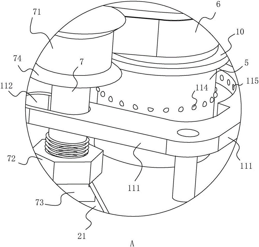
[0042] Such as figure 1 and figure 2 As shown, a tensioning device is provided on the base pl...

Embodiment 2

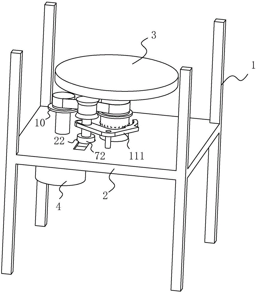
[0051] Embodiment two: a kind of asphalt rotary compactor, such as figure 2 As shown, the difference from Embodiment 1 is that the fixing piece 72 is slidably connected to the tension adjusting rod 7, and the bottom plate 2 is provided with a notch 22 matching with the fixing piece 72, and the fixing piece 72 is fitted into the notch 22. Inside.

[0052] When the transmission belt 6 is tensioned, slide the fixing part 72 to make it embed in the notch 22, and then the tension adjusting rod 7 can be fixed; Make drive belt 6 slack.

Embodiment 3

[0053] Embodiment three: a kind of asphalt rotary compactor, such as Figure 4 and Figure 5 As shown, the difference from Embodiment 1 is that the fixing member 72 is a fixing clip 8, and the fixing clip 8 includes two splints that are rotatably connected to the bottom plate 2, and the two splints can be rotated to a position that is relatively close to and away from each other. To realize the clamping and relaxation of the tension adjustment rod 7; the end of the fixed clip 8 is provided with a bayonet 81 that matches the tension adjustment rod 7, and when the fixed clip 8 clamps the tension adjustment rod 7, the tension adjustment rod 7 is placed In the bayonet 81, the tension adjustment rod 7 is restricted and cannot slide, so that the transmission belt 6 can realize more stable power transmission; the bottom plate 2 is connected with a pin block 9 in rotation, and the pin block 9 rotates in the vertical direction, and the pin block 9 9 is an L-shaped structure, which has...


PUM


Abstract

The invention discloses a pitch gyratory compactor, aims at solving the defects that an existing gyratory compactor is difficult to brake, and is technically characterized in that the pitch gyratory compactor comprises a bottom plate, a rotary table and a driving motor for driving the rotary table to rotate, wherein the rotary table is fixedly connected with a roller, the roller is rotationally connected with the bottom plate, a spindle of the driving motor penetrates through the bottom plate, and is fixedly provided with a driving wheel, the driving wheel and the roller are provided with a driving belt, used for realizing power transmission, in a sleeving manner, and the bottom plate is provided with a tension device for controlling the tightness of the driving belt. The pitch gyratory compactor is convenient to brake and also improves the detection efficiency for road samples, so that data about various properties of road surfaces can be quickly and accurately obtained, thereby providing effective reference value for road construction.

Description

technical field [0001] The invention relates to the technical field of road material detection auxiliary tooling, more specifically, it relates to an asphalt rotary compactor. Background technique [0002] In road construction projects, it is necessary to compact pavement material samples into various test pieces in order to analyze the characteristics of pavement materials. In the compaction process, in order to better simulate the compaction effect of the wheels on the road surface, it is necessary to use a gyratory compactor to compact the specimen while rotating. At present, the widely used gyratory compactor is generally composed of a radially rotating tray part and a pressure plate part which reciprocates up and down for compaction, and the pressure plate is generally arranged horizontally. Due to the complex force on the actual road surface, the vertical force given to the test piece by the pressure plate is quite different from the force on the actual road surface, ...

Claims


Application Information

Patent Timeline
Patent Type & Authority Applications(China)
IPC IPC(8): G01N1/28
CPCG01N1/286
Inventor 金锋金玮
Owner 昆山市交通工程集团有限公司
Why Eureka
Try Eureka