Device and method for measuring cracking pressure of a carbon dioxide cracker

A carbon dioxide and measuring device technology, which is applied in the direction of measuring devices, instruments, scientific instruments, etc., can solve the problem of lack of special research on carbon dioxide fracturing pressure, which affects the fragmentation effect and energy utilization rate of carbon dioxide phase change fracturing technology, and the measured data is ambiguous And other problems, to achieve the effect of preventing the flying tube phenomenon, preventing the rapid attenuation of energy, and high accuracy

Active Publication Date: 2019-07-23
CENT SOUTH UNIV
View PDF4 Cites 0 Cited by
  • Summary
  • Abstract
  • Description
  • Claims
  • Application Information

AI Technical Summary

Problems solved by technology

[0004] In addition, phase change fracturing technology is a new type of physical blasting technology. Compared with traditional blasting technology, it has the advantages of no pollution, low price, low noise, small vibration, safety and reusability. It can be used in urban demolition blasting, subway Blasting, tunneling blasting, and mining blasting have great room for development, but there are few special studies on carbon dioxide fracture pressure. Generally, some empirical values ​​are obtained according to conventional on-site detection methods, while conventional in-hole detection The method is based on an ideal environment and does not consider the influence of geological structure and rock properties, which makes the measured data ambiguous and does not have an exact value, which seriously affects the fragmentation effect and energy utilization rate of carbon dioxide phase change fracturing technology.

Method used


Image

  • Device and method for measuring cracking pressure of a carbon dioxide cracker
  • Device and method for measuring cracking pressure of a carbon dioxide cracker
  • Device and method for measuring cracking pressure of a carbon dioxide cracker

Examples


Embodiment Construction

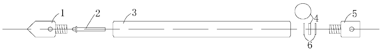
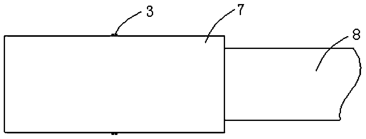
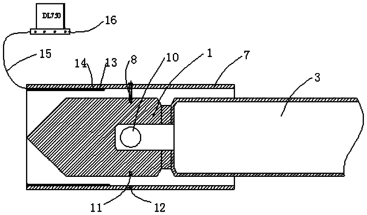
[0038] see figure 2 and image 3 , the cracking pressure testing device of a carbon dioxide cracker in this example is a preferred embodiment of the present invention, specifically including an energy dissipation cover 7, a fixing screw 8, an energy dissipation head 1, a PVDF piezoelectric film sensor 13, a tin foil Adhesive tape 14, signal line 15 and oscilloscope 16.

[0039] Energy release cover 7 adopts seamless steel pipe parts, and fixed cover is contained in figure 1 On the energy-discharging head 1 of the cracker, two energy-discharging holes 10 are arranged at intervals of 180° on the same circumference of the energy-discharging head 1, and the high-pressure gas inside the cracker enters from the two energy-discharging holes 10 In the energy-discharging cover 7, an instantaneous impact is formed on the inside of the energy-discharging cover 7, and then the pressure is released from the openings at both ends of the energy-discharging cover 7.

[0040] The energy re...


PUM

PropertyMeasurementUnit
thicknessaaaaaaaaaa
diameteraaaaaaaaaa
depthaaaaaaaaaa

Abstract

The invention discloses a fracturing pressure determining device and method for a carbon dioxide fracturing device. The device comprises an energy leaking cover, a pressure sensor and a signal collecting unit, the energy leaking cover is of a barrel-shaped structure with openings in two ends, the energy leaking cover is installed on an energy leaking head of the fracturing device through an open cover at one end in an opposite-fixation mode, and the pressure sensor is attached to the inner wall of the energy leaking cover and is in signal connection with the signal collecting unit. Through the pressure sensor, during high-speed gasification of liquefied carbon dioxide, a fracturing pressure signal of the fracturing device is measured and transmitted to the signal collecting unit. The fracturing pressure determining device is mainly used for accurately measuring the fracturing pressure of the carbon dioxide fracturing device. The device carries out an experiment conveniently, is easy to operate and accurate and reliable in measurement result, provides possibility for accurate calibration of the liquefied carbon dioxide, and not only can provide reliable data for designing and producing of fracturing devices of different dimensions, but also can analyze and research the change relation between fracturing pressure and distance, so that the utilization rate of energy is increased.

Description

technical field [0001] The present invention relates to a cracking pressure measurement device and method of a carbon dioxide cracker, in particular to a method for directly measuring the impact of high-pressure gas on the surrounding space or during the process of instantaneous gasification of liquid carbon dioxide and high-speed release from the energy release hole of the cracker. A device and method for the magnitude of the pressure of a substance. Background technique [0002] Carbon dioxide phase change fracturing technology was originally developed by the United Kingdom in the 1950s. It was mainly used as a coal and rock crushing method for high-gas wells to replace explosives, increase the lump coal rate, and avoid gas explosions. Later, due to the advent of large-scale fully mechanized mining equipment, safe and efficient non-explosive coal mining operations were realized and gradually replaced CO 2 Disguised blasting technology; since then, this technology has been...

Claims


Application Information

Patent Timeline
Patent Type & Authority Patents(China)
IPC IPC(8): G01N3/313
CPCG01N3/313G01N2203/0019G01N2203/0044G01N2203/0629
Inventor 陶明赵华涛李夕兵马敖褚夫蛟
Owner CENT SOUTH UNIV
Why Eureka
Try Eureka