
Monitoring method for short-circuit fault between stator core and through-hole screw of synchronous generator

A synchronous generator and stator core technology, applied in short-circuit testing, measuring electricity, measuring devices, etc., can solve the problems of inability to respond sensitively to short-circuit faults, failure to detect faults in time, and short-circuit faults of stator slots, and achieve full coverage detection. , The effect of preventing large-scale melting of the stator core and finding faults in time

Active Publication Date: 2021-02-19
NORTH CHINA ELECTRIC POWER UNIV (BAODING)
View PDF6 Cites 0 Cited by
  • Summary
  • Abstract
  • Description
  • Claims
  • Application Information

AI Technical Summary

Problems solved by technology

This method has been widely adopted by the international electric power industry. However, this method also has obvious disadvantages, that is, it can only find the short-circuit fault of the stator tooth slot, and cannot respond sensitively to the short-circuit fault between the through-hole screw and the stator core.
[0007] To sum up, currently there are only detection methods for diagnosing the insulation state of the core screw and the short-circuit fault of the stator core, and they are all offline detection methods, which cannot detect the fault in time and may lead to the deterioration of the fault
Among them, neither the iron loss test method nor the ELCID method can find the short-circuit fault between the through-hole screw and the stator core located deep in the stator core, and the short-circuit fault between the through-hole screw and the stator core is precisely the one with the highest occurrence rate and the most destructive Therefore, it is necessary to develop an online, high-sensitivity detection method for the short-circuit fault between the core screw and the stator core.

Method used


Image

  • Monitoring method for short-circuit fault between stator core and through-hole screw of synchronous generator
  • Monitoring method for short-circuit fault between stator core and through-hole screw of synchronous generator
  • Monitoring method for short-circuit fault between stator core and through-hole screw of synchronous generator

Examples


Embodiment Construction

[0027] The standard parts used in the present invention can be purchased from the market, and the special-shaped parts can be customized according to the instructions and the accompanying drawings. The specific connection methods of each part adopt mature bolts, rivets, welding in the prior art , pasting and other conventional means, no longer described in detail here.

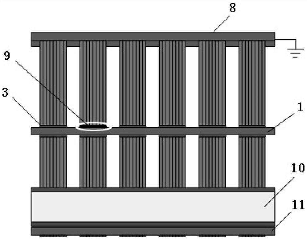
[0028] A method for monitoring the short-circuit fault between the stator core and the core screw of a synchronous generator. The core screw 1 of the stator core of the synchronous generator is connected to the ground through a high-resistance resistor 12 and a sampling resistor 13 connected in series, and a data acquisition and analysis device 5 is used online. Collect the instantaneous voltage value at both ends of the sampling resistor 13, compare the instantaneous voltage value with the fault judgment threshold, and when it exceeds the fault judgment threshold, it is judged that the synchronous generator ha...


PUM


Abstract

The invention discloses a method for monitoring a short-circuit fault between a stator core and a cross-core threaded rod in a synchronous generator. A high-resistance resistor and a sampling resistor are connected with the ground, wherein the high-resistance resistor and the sampling resistor are in series connection and connected to the cross-core threaded rod which is arranged in the stator core in the synchronous generator; a momentary value of voltage across two ends of the sampling resistor are collected online, the momentary value of the voltage is compared with a fault determining threshold value, and when the momentary value of the voltage exceeds the fault determining threshold value, it is determined that the short-circuit fault occurs between the stator core and the cross-core threaded rod in the synchronous generator. The method can solve the deficiency in the prior art and improve the diagnostic ability of such faults.

Description

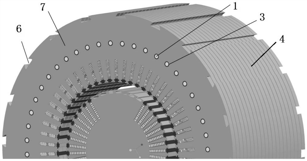
technical field [0001] The invention relates to the technical field of generators, in particular to a monitoring method for a short-circuit fault between a stator iron core and a through-hole screw of a synchronous generator. Background technique [0002] The stator core of the synchronous generator is made of silicon steel punched sheets stacked together. In order to prevent the core punched sheets from shifting and vibrating during operation and cutting the insulation of the stator winding, it is necessary to apply axial pressure to the core punched sheets with the help of a through-core screw to make the core punched sheets fasten. In order to prevent overheating damage caused by local eddy current or circulating current caused by the short circuit of the iron core punching sheet, an insulating material is set between the core screw and the punching sheet, see figure 1 . [0003] In order to avoid the short circuit of the core screw through the pressure ring and other s...

Claims


Application Information

Patent Timeline
Patent Type & Authority Patents(China)
IPC IPC(8): G01R31/52
CPCG01R31/50
Inventor 武玉才徐乾杰马明晗马倩倩
Owner NORTH CHINA ELECTRIC POWER UNIV (BAODING)
Learn More