
Liquid crystal waveguide adjustable optical delay line and continuous delay quantity adjustment method

A delay line and waveguide technology, applied in the field of optical communication, can solve the problems of not being able to change continuously, the accuracy of fiber cutting technology is limited, and the minimum delay difference can only be stepped, etc., to achieve the effect of fast adjustment speed

Inactive Publication Date: 2017-05-31
CHINA WEST NORMAL UNIVERSITY
View PDF6 Cites 1 Cited by
  • Summary
  • Abstract
  • Description
  • Claims
  • Application Information

AI Technical Summary

Problems solved by technology

Due to the limited accuracy of optical fiber cutting technology, the minimum length difference between two sections of optical fiber is ≥1mm, resulting in a minimum delay difference that can only be stepped (about 5ps) and cannot be adjusted continuously. Therefore, the optical delay line unit is controlled by changing the length of the optical fiber The amount of delay is stepped and cannot be changed continuously; the phase control array composed of optical delay line units can only work in a stepwise manner, resulting in the inability to realize continuous scanning of the beam space, resulting in blank spots in the monitoring range of the phased array radar

Method used


Image

  • Liquid crystal waveguide adjustable optical delay line and continuous delay quantity adjustment method
  • Liquid crystal waveguide adjustable optical delay line and continuous delay quantity adjustment method
  • Liquid crystal waveguide adjustable optical delay line and continuous delay quantity adjustment method

Examples


Embodiment Construction

[0022] The implementation of the present application will be described in detail below in conjunction with the accompanying drawings, so that the realization process of how the present application uses technical means to solve technical problems and achieve technical effects can be fully understood and implemented accordingly.

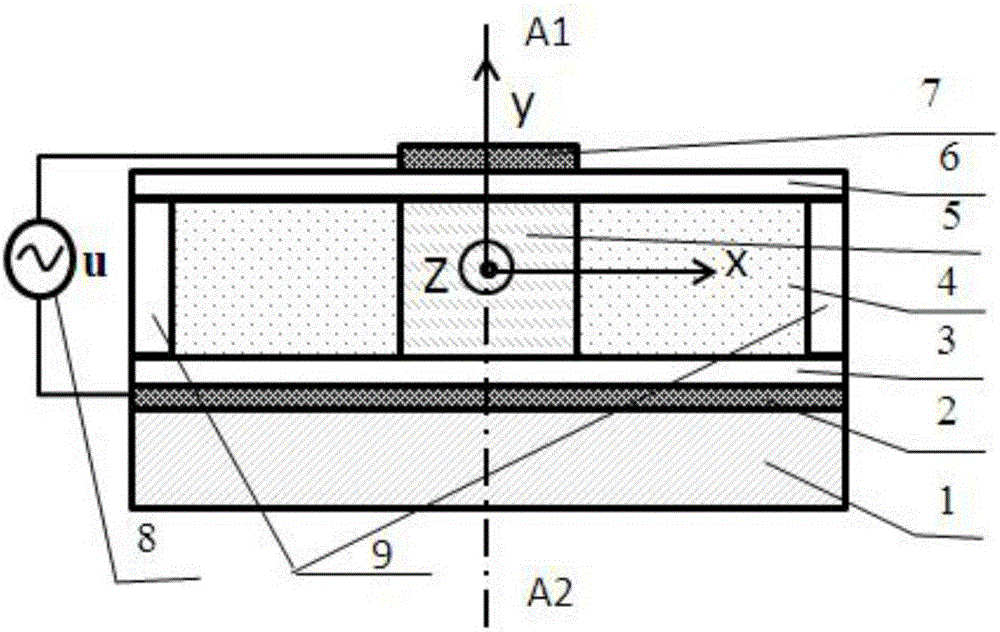
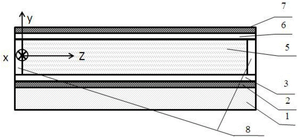
[0023] The present invention will be described in detail below in conjunction with accompanying drawing, as figure 1 As shown, the liquid crystal waveguide adjustable optical delay line provided by the present invention includes a glass substrate 1, an adjustment mechanism, a waveguide system, and a signal voltage source 8. The adjustment mechanism is composed of a lower electrode 2 and an upper electrode 7. The waveguide system It consists of a waveguide lower cladding layer 3, a waveguide upper cladding layer 6, a liquid crystal waveguide layer 4, and a liquid crystal waveguide core 5. The waveguide lower cladding layer 3, waveguide upper cladding lay...


PUM


Abstract

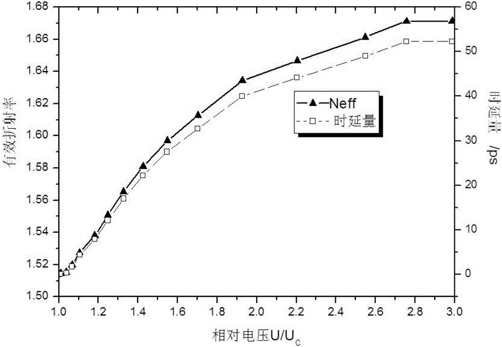
The invention discloses a liquid crystal waveguide adjustable optical delay line and a continuous delay quantity adjustment method. The liquid crystal waveguide adjustable optical delay line comprises a glass substrate, an adjustment mechanism, a waveguide system and a signal voltage source. The adjustment mechanism consists of a lower electrode and an upper electrode, the waveguide system comprises a waveguide coating layer, a liquid crystal waveguide layer and a liquid crystal waveguide core. The glass substrate serves as a physical support for a whole device and supports the lower electrode of the adjustment mechanism, the waveguide system and the upper electrode of the adjustment mechanism sequentially from bottom to top. Positive and negative poles of external control voltage signals are connected with the upper electrode and the lower electrode of the adjustment mechanism respectively, and the liquid crystal waveguide layer is mounted in a liquid crystal box which is formed by an upper waveguide coating layer, a lower waveguide coating layer and left and right side walls. A deflection angle of a liquid crystal molecule long axis of the liquid crystal waveguide core is beta, and an effective refractive index of a y-direction polarization light wave mode in the liquid crystal waveguide core is Neff. The liquid crystal waveguide adjustable optical delay line is continuously adjustable in delay difference and high in adjustment speed which reaches the microsecond magnitude.

Description

technical field [0001] The application belongs to the technical field of optical communication, and in particular relates to a liquid crystal waveguide adjustable optical delay line and a method for continuously adjusting the delay amount. Background technique [0002] An optical delay line is a photonic device that delays optical signal transmission, and an adjustable optical delay line is a photonic device that can adjust the length of optical signal transmission delay time with a control amount. A common optical delay line is an optical fiber delay line. It takes a certain amount of time for an optical signal to be transmitted from one end of a certain length of optical fiber to the other end. The length of time consumed is the time delay (referred to as delay). Different lengths of optical fibers have different time delays, resulting in a phase difference between the signals carried on the light waves, causing changes in the synthesized signal waveform and spatial orient...

Claims


Application Information

Patent Timeline
IPC IPC(8): G02F1/1343G02F1/1333G02F1/133
CPCG02F1/13306G02F1/1333G02F1/134309
Inventor 张谦述
Owner CHINA WEST NORMAL UNIVERSITY
Learn More