Crane wheel load testing device and method

A testing device and a crane technology, applied in measuring devices, force/torque/work measuring instruments, measurement of changes in magnetic properties of materials caused by applied stress, etc., can solve the difficulties of accurate measurement or theoretical calculation, and cannot meet Optimal performance and lightweight requirements of hoisting machinery

Pending Publication Date: 2017-05-31
SPECIAL EQUIP SAFETY SUPERVISION INSPECTION INST OF JIANGSU PROVINCE
View PDF7 Cites 3 Cited by
  • Summary
  • Abstract
  • Description
  • Claims
  • Application Information

AI Technical Summary

Problems solved by technology

[0009] At present, domestic designers use empirical formulas and data based on classical mechanics, which cannot meet the requirements of optimal performance and lightweight design of hoisting machinery
Engineering practice requires a more accurate maximum wheel pressure value, but now most crane wheel pressure distribution is statically indeterminate, and its distribution is related to the structure of the crane, foundation stiffness, manufacturing accuracy and track flatness, so direct accurate measurement or theoretical calculation is required It is very difficult, so it is necessary to study a method and device that can accurately and conveniently test the maximum wheel pressure of hoisting machinery

Method used


Image

  • Crane wheel load testing device and method
  • Crane wheel load testing device and method
  • Crane wheel load testing device and method

Examples


Embodiment 1

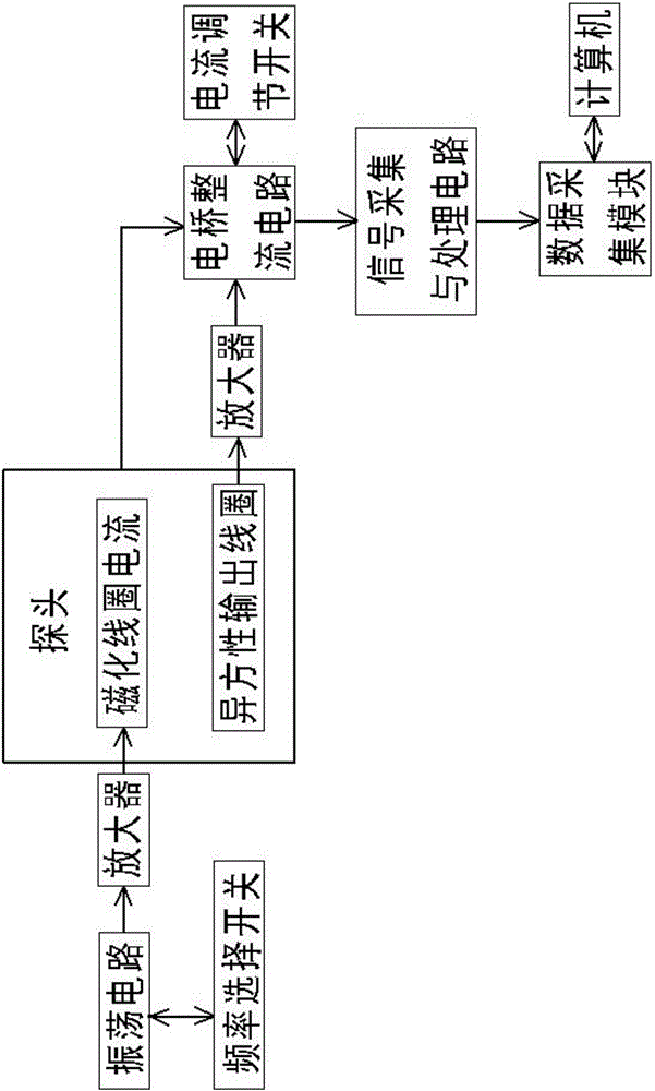
[0091] Embodiment 1. refer to figure 1 , a crane wheel pressure test device:

[0092] It includes a probe, the probe is a magnetic stress sensor, and the magnetic stress sensor includes a magnetized coil current and an anisotropic output coil for extracting electrical signals of the anisotropic effect of the magnetic properties of the measured point;

[0093] The device is also provided with an oscillating circuit, and the oscillating circuit is connected with the magnetizing coil current through the amplifying circuit; the anisotropic output coil is connected to the bridge rectifying circuit through the amplifying circuit, and the magnetizing coil current is also connected with the bridge rectifying circuit The bridge rectifier circuit is connected to the signal acquisition and processing circuit; the other end of the signal acquisition and processing circuit is also connected to a data acquisition module, and the data acquisition module is connected to the computer system....

Embodiment 2

[0095] Embodiment 2, with reference to figure 2 , a crane wheel pressure testing method, its steps are as follows:

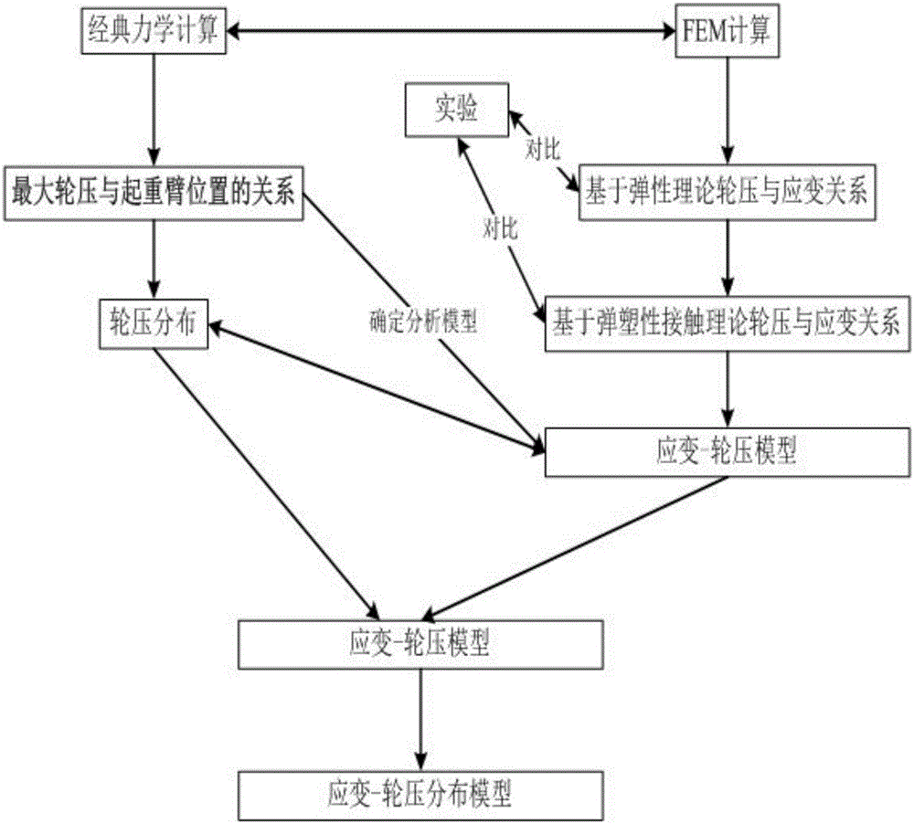
[0096] (1) Through calculation, the maximum wheel pressure is obtained when the boom is parallel to the track, and the overall finite element model of the crane is established according to the determined relationship between the maximum wheel pressure and the position of the boom; through classical theory and finite element analysis and calculation, it is obtained Wheel pressure distribution law: The wheel pressure distribution of each wheel of the crane is different, the wheel pressure of each wheel of the driving wheel group is nearly the same, and the wheel pressure of each wheel of the driven wheel group is approximately the same; As the hoisting weight increases, the wheel pressure of the wheel set closer to the boom is getting larger, while the wheel pressure of the farther wheel set is getting smaller and smaller;

[0097] (2) Establish a strain-wheel p...

Embodiment 3

[0118] Embodiment 3, MQ12-33 type gantry crane maximum wheel pressure measurement method experiment:

[0119] Principle: The crane wheel is the only part that transmits force between the crane and the track. The force on the wheel is wheel pressure, the wheel and rail contact, and contact force is generated in the contact area. At this time, the track deforms and strains, and the track magnetic field changes accordingly. Dynamic The signal test and analysis system converts the magnetic field change into a stress value and records it, and then converts the stress into a strain according to the strain-stress relationship, and then calculates the wheel pressure according to the strain-wheel pressure model of the present invention. Its working principle is as follows Figure 11 shown.

[0120] Using the method of the present invention to measure the maximum wheel pressure of a port MQ12-33 portal crane comprises the following steps:

[0121] MQ12-33 gantry crane parameters: rated...


PUM

PropertyMeasurementUnit
Yield stressaaaaaaaaaa
Elastic modulusaaaaaaaaaa

Abstract

Provided is a crane wheel load testing device. The device comprises a magnetized coil current and an anisotropic property output coil used for extracting magnetic characteristic anisotropic effect of a tested point; the device is further provided with an oscillating circuit, and the oscillating circuit is connected to the magnetized coil current through an amplifying circuit; the anisotropic property output coil is connected to a bridge rectifier circuit through the amplifying circuit, the magnetized coil current is also electrically connected to the bridge rectifier circuit, and the bridge rectifier circuit is connected to a signal acquisition and processing circuit; the other end of the signal acquisition and processing circuit is further in communication connection to a data acquisition module, and the data acquisition module is in communication connection to a computer system. The invention further discloses a crane wheel load testing method. According to the crane wheel load testing device and method, there is no need for surface treatment, non-contact measuring can be achieved, the measuring efficiency is high, the result is an absolute value, the measuring method is simple, there is no consumed materials, the measuring cost is low, the measuring precision is high, and measuring to the distribution of crane wheels can be achieved.

Description

technical field [0001] The invention relates to a wheel pressure test device, in particular to a crane wheel pressure test device, and also relates to a method for using the device to perform wheel pressure test. Background technique [0002] Crane wheel pressure is a key important parameter in the design of hoisting machinery, generally refers to the vertical pressure of a wheel on the ground or rail surface. The maximum value of the wheel pressure not only affects the mechanism design of the crane, such as the size and number of wheels, but also affects the design of the bridge frame, gantry structure and foundation pressure bearing capacity of the crane. [0003] In traditional crane design, the wheel pressure is calculated according to the static balance equation based on the crane’s self-weight, span, hoisting weight, etc. according to the design manual; The distribution of is also related to the rigidity of the structure, so the accuracy of the wheel pressure value ca...

Claims


Application Information

Patent Timeline
IPC IPC(8): G06F17/50G01L1/12G01L5/00
CPCG01L1/12G01L5/00G06F30/23G06F30/17Y02T90/00
Inventor 张志斌张华民钱明佺葛藤殷春浩
Owner SPECIAL EQUIP SAFETY SUPERVISION INSPECTION INST OF JIANGSU PROVINCE
Why Eureka
Try Eureka