Electromagnetic emission presentation device

A demonstration device and electromagnetic technology, applied in educational appliances, instruments, teaching models, etc., can solve the problems of insufficient output power, low initial speed of bore, and high repair rate, to prevent instantaneously excessive surge current and improve learning effect. , Use safe and reliable effect

Inactive Publication Date: 2017-05-31
江苏科学梦创展科技有限公司
View PDF6 Cites 2 Cited by
  • Summary
  • Abstract
  • Description
  • Claims
  • Application Information

AI Technical Summary

Problems solved by technology

[0003] Electromagnetic guns used in scientific and educational experiments in the prior art have the following disadvantages: 1. When used in military and other research fields, it is difficult for ordinary study visitors to experience the experiment and display process of electromagnetic guns; 2. The cost is huge and the manufacturing process is complicated. , Non-professional organizations are not enough to make and produce electromagnetic guns; 3. Without protective measures, "cannonballs" are easy to hurt people, and the "cannonballs" recovery device cannot be recycled; 4. The energy loss is large and the output power is insufficient, which is easy to cause The initial velocity of the "cannonball" is small, which is not enough to demonstrate the power of the electromagnetic gun; 5. The structural stability of the entire electromagnetic gun is low, and it cannot meet the long-term circular demonstration. It is easily damaged and has a high repair rate

Method used


Image

  • Electromagnetic emission presentation device
  • Electromagnetic emission presentation device
  • Electromagnetic emission presentation device

Examples


Embodiment Construction

[0026] The present invention will be further described in detail below with reference to the accompanying drawings, so that those skilled in the art can implement it with reference to the text of the description.

[0027] It should be understood that terms such as "having", "including" and "including" used herein do not equate the presence or addition of one or more other elements or combinations thereof.

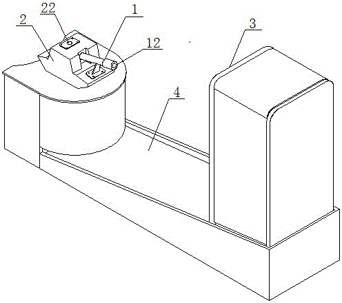
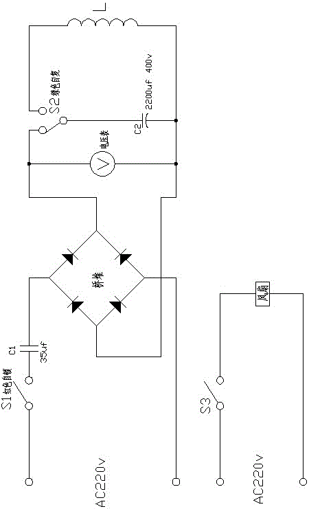
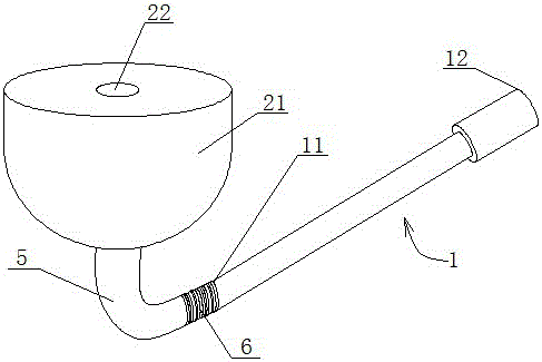
[0028] Figure 1 to 4 An implementation form according to the present invention is shown, which includes: a barrel 1 having a tubular structure with an entrance 11 and an exit 12 of the projectile, and the barrel 1 is movably mounted on the turret 2, The gun barrel 1 realizes multi-angle adjustment on the gun turret 2. The gun turret 2 has a bullet cavity 21 inside, the outer wall of the bullet cavity 21 of the gun 2 is provided with a bullet filling port 22, and the gun barrel 1 is wound with a coil L. L is connected to the two ends of the 2200uf capacitor C2, the two ends of ...


PUM


Abstract

The invention discloses an electromagnetic emission presentation device, comprising a gun barrel, a battery, a discharge circuit, and a charge circuit. The gun barrel is provided with tubular structures of an entrance port and an exit port of a shell; the battery is internally hollow and used for placing metal shell, wherein the entrance port of the shell is connected with the inner part of the battery, and the gun barrel is moveably installed on the battery, and the gun barrel can realize the adjustment at many angles on the battery; the discharge circuit has a coil and a first capacitor, both ends of the coil are connected to positive and negative electrode plates of the first capacitor, and the coil is wound on the gun barrel; the charge circuit is provided with a bridge pile, and two input end of the bridge pile are connected with power source, and two output ends of the bridge pile are connected to the positive and negative electrode plates of the first capacitor, wherein a shell filling opening is arranged on the battery and used for placing the shell in the inner part of the battery. By using the electromagnetic effect principle, the device generates big magnetism, thus the shell can be shot by dynamic energy, the device is ingenious in structure, simple in operation; the device adds the interestingness, improves the study effect, repeatedly displays operation, and improves the display effect.

Description

Technical field [0001] The invention relates to a device used in scientific and educational experiments and entertainment activities. More specifically, the present invention relates to an electromagnetic emission demonstration device for scientific and educational experiments. Background technique [0002] Electromagnetic gun is a weapon that uses electromagnetic force (Lorentz force) to launch cannonballs along a rail. It is mainly composed of three parts: energy, accelerator and switch. The energy source is usually a device that can store 10-100 megajoules of energy. The current experimental energy sources include battery packs, magnetic flux compression devices, and unipolar generators, among which unipolar generators are the most promising energy source. The accelerator is a device that converts electromagnetic energy into the kinetic energy of the projectile so that the projectile reaches a high speed. There are two main categories: railgun accelerators powered by low-...

Claims


Application Information

Patent Timeline
Patent Type & Authority Applications(China)
IPC IPC(8): G09B23/18
CPCG09B23/181
Inventor 祁劲鹏
Owner 江苏科学梦创展科技有限公司
Why Eureka
Try Eureka