
Liquid direct contact type cooling device

A cooler and contact technology, which is applied in the direction of electric solid devices, semiconductor devices, semiconductor/solid device components, etc., can solve the problems of large contact thermal resistance, liquid leakage, and inability to dissipate heat from high-power devices, so as to improve heat dissipation efficiency effect

Pending Publication Date: 2017-05-31
广东西江数据科技有限公司
View PDF4 Cites 1 Cited by
  • Summary
  • Abstract
  • Description
  • Claims
  • Application Information

AI Technical Summary

Problems solved by technology

When the air-cooled heat dissipation mode is adopted, the specific heat capacity of the air is small, and the heat taken away by the air is relatively small. Facing the power devices with increasingly compact structure and increasing power, the air-cooled heat dissipation mode cannot meet the heat dissipation requirements
When the water-cooled plate radiator is used, the high-power devices are directly attached to the surface of the water-cooled plate radiator, and the heat is dissipated through the circulating flow of cooling water. On the one hand, this heat dissipation method may cause liquid leakage to cause shutdown, and on the other hand, the water-cooled substrate The scale formed by the long-term use of the radiator will greatly reduce the thermal conductivity, and the contact thermal resistance is large, which cannot meet the heat dissipation requirements of high-power devices

Method used


Image

  • Liquid direct contact type cooling device
  • Liquid direct contact type cooling device
  • Liquid direct contact type cooling device

Examples


Embodiment 1

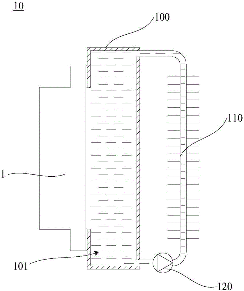
[0037] Please refer to figure 1 , this embodiment provides a liquid immersion cooler 10 for heat dissipation of a power device 1 , including a cooler body 100 , a heat exchange structure 110 and a circulation pump 120 .

[0038] The cooler body 100 has a cooling cavity 101 and a cooling port communicating with the cooling cavity 101 . The heat dissipation opening is disposed at a middle portion of a side wall of the cooler body 100 . The cooling cavity 101 is used for filling the insulating and heat-conducting liquid, and for making the insulating and heat-conducting liquid directly contact the heat-dissipating surface of the power device through the heat dissipation opening. The cooler body 100 at least surrounds the peripheral portion of the heat dissipation opening and is sealingly fitted with the heat dissipation wall through an insulating sealant layer.

[0039] The liquid inlet of the heat exchange structure 110 is connected with the liquid outlet of the cooler body 100,...

Embodiment 2

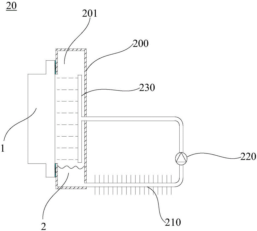
[0043] Please refer to figure 2 , this embodiment provides a liquid spray cooler 20 for heat dissipation of the power device 1 , including a cooler body 200 , a heat exchange structure 210 , a circulation pump 220 and a spray structure 230 .

[0044] The cooler body 200 has a cooling cavity 201 and a cooling port communicating with the cooling cavity 201 . The heat dissipation opening is arranged in the middle of a side wall of the cooler body 200, and the cooler body 200 at least surrounds the peripheral portion of the heat dissipation opening for sealing fit with the heat dissipation wall through an insulating sealant layer. The cooling channel of the heat exchange structure 210 communicates with the cooling cavity 201 through a return pipe. The heat exchange structure 210 exchanges heat through water cooling. The circulation pump 220 is arranged on the return pipeline, and is used to make the cooling medium 2 flowing out of the cooling cavity 201 flow back into the cooli...

Embodiment 3

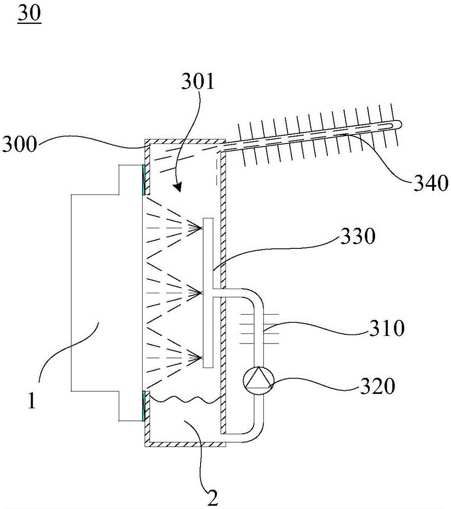
[0048] Please refer to image 3 , this embodiment provides a liquid spray cooler 30 for heat dissipation of the power device 1, including a cooler body 300, a first heat exchange structure 310, a circulation pump 320, a spray structure 330 and a second heat exchange structure 340 .

[0049] The cooler body 300 has a cooling cavity 301 and a cooling port communicating with the cooling cavity 301 . The heat dissipation opening is arranged in the middle of a side wall of the cooler body 300 , and the cooler body 300 at least surrounds the peripheral portion of the heat dissipation opening for sealing fit with the heat dissipation wall through an insulating sealant layer. The cooling channel of the first heat exchange structure 310 communicates with the cooling cavity 301 through a return pipe. The heat exchange structure 310 exchanges heat through water cooling. The circulation pump 320 is arranged on the return pipeline, and is used to make the cooling medium 2 flowing out of...


PUM


Abstract

The invention relates to a liquid direct contact type cooling device. The liquid direct contact type cooling device comprises a cooling device body, a heat exchanging mechanism and a circulating pump, wherein the periphery of the connector of the cooling device body is used for being coordinated with a power device to seal a cooling cavity, and the cooling cavity of the cooling device body and the heat exchanging structure can allow cooling media to form a circulating loop through the circulating pump. During work, the cooling media in the direct contact type cooling device can directly contact with the radiating surface of the power device to take away heat; compared with a radiating manner with low specific heat capacity, the liquid direct contact type cooling device eliminates the contact heat resistance between the radiating surface of a traditional power device and the radiating plate of a cooling device and can evidently increase heat transfer performance; the heat exchanging structure can constantly take away the heat by the circulating flowing of the cooling media, and the overall radiating efficiency of the power device is increased greatly. In addition, the liquid direct contact type cooling device can allow the temperature of the radiating surface of the power device to be even and prolong the service life of the power device.

Description

technical field [0001] The invention relates to the technical field of cooling of power devices, in particular to a liquid direct contact cooler. Background technique [0002] In actual work, the heat generated by highly integrated high-power devices will increase the temperature of the chip. If the heat dissipation is slow, the temperature of the chip may rise to exceed the maximum allowable junction temperature, and the performance of the device will be significantly reduced, and It cannot work stably, and may even burn out directly. Therefore, controlling the heating rate of high-power devices to keep the internal temperature of the chip within the allowable junction temperature and ensure the stable operation of the machine has become the focus and difficult problem in the field of high-power device technology research. [0003] Since power devices need insulation protection, the heat dissipation of power devices mostly adopts air-cooled heat dissipation mode and water-...

Claims


Application Information

Patent Timeline
IPC IPC(8): H01L23/427H01L23/473
CPCH01L23/427H01L23/473H01L23/4735
Inventor 王伟吕松浩李雪徐凌燕
Owner 广东西江数据科技有限公司
Learn More