Linear vibrating motor

A linear vibration and motor technology, applied in the field of motors, can solve the problems of not reducing the vibration amplitude and reducing the size of the motor, and achieve the effect of ensuring normal operation, low resistance and low power consumption

Pending Publication Date: 2017-05-31
WENZHOU FUERTE ELECTRONICS TECH CO LTD
View PDF9 Cites 3 Cited by
  • Summary
  • Abstract
  • Description
  • Claims
  • Application Information

AI Technical Summary

Problems solved by technology

[0005] Therefore, the technical problem to be solved by the present invention is to overcome the problem that the linear vibration motor in the prior art is difficult to meet the problem of reducing the volume of the motor without reducing the vibration amplitude.

Method used


Image

  • Linear vibrating motor
  • Linear vibrating motor
  • Linear vibrating motor

Examples


Embodiment 1

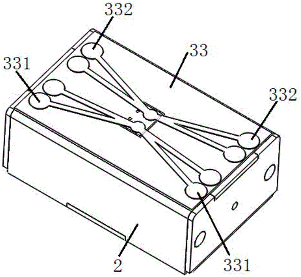
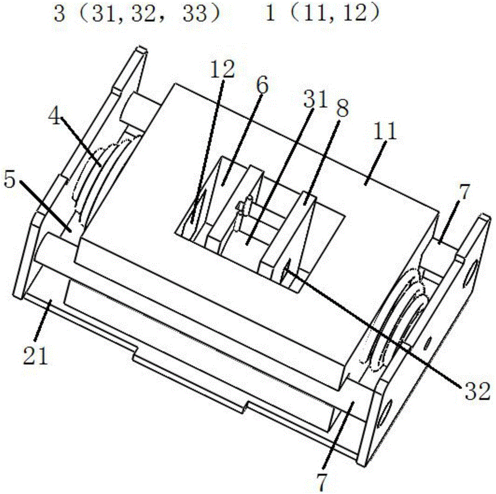
[0062] This embodiment provides a linear vibration motor, such as figure 1 with figure 2 As shown, it includes a housing 2 , a vibrating assembly 1 , a stator assembly 3 , two elastic components 4 , a guiding structure and a fixing mechanism 8 . Under the cooperation of the two elastic components 4 and the stator assembly 3 , the mass block 11 can be driven to make reciprocating linear motion along its length direction.

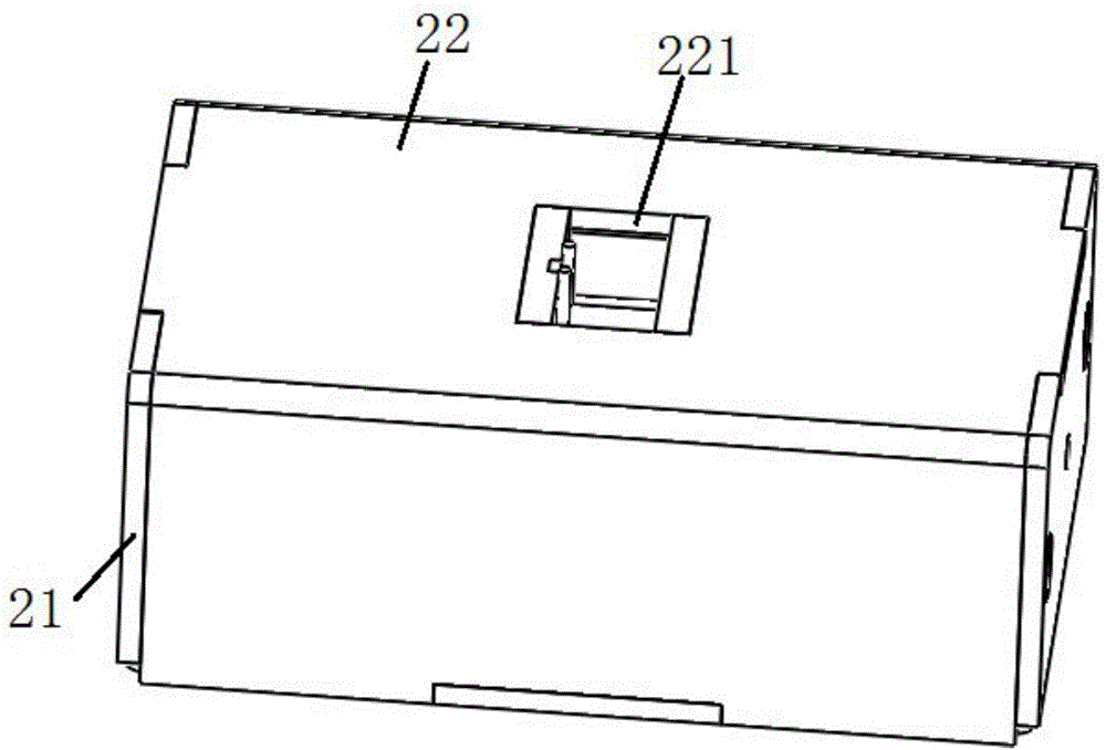
[0063] Such as image 3 with Figure 4 As shown, the housing 2 has an installation cavity, including a base 21 and an upper casing 22 mounted on the base 21, wherein the base 21 includes a bottom plate and a first vertical plate (such as Such as figure 1 The left and right side walls in the middle); the upper casing 22 includes a top plate and a second vertical plate (for example, which is fixed on the two side walls of the top plate and extends downward figure 1 The front and rear side walls in the middle), two second vertical plates are vertically ins...

Embodiment 2

[0087] This embodiment provides a linear vibration motor, such as Figure 9-Figure 12 As shown, the difference with the linear vibrating motor provided in Embodiment 1 is only:

[0088] Under the action of external force, the first part 41 and the transition section 43 of the elastic member 4 can be compressed toward the second part 42 and embedded in the second part 42; Extend and drive the mass 11 to move away from the second part 42 .

[0089] Such as Figure 10 , Figure 12 with Figure 13 As shown, the elastic member 4 is also preferably a tower spring, and the setting direction of the tower spring in Embodiment 1 is just opposite, the tower top of the tower spring is used as the first part 41, and the tower bottom is used as the second part 42, and the outer shell Two vertical limiting protrusions 212 are formed on the inner wall surface, the second part 42 of the tower spring is located between the two limiting protrusions 212 and abuts against the inner wall surfac...


PUM


Abstract

The invention discloses a linear vibrating motor. The linear vibrating motor comprises a casing, a vibration assembly, a stator assembly and elastic components, wherein the vibration assembly comprises a mass block and magnets symmetrically embedded in the mass block; a first through hole is formed between two magnets in the mass block; the stator assembly comprises a coil located in the first through hole and a magnetism increasing component arranged in the coil; second gaps are reserved between two ends of the coil and two side wall surfaces of the first through hole; first gaps are formed between two ends of the mass block and the inner wall surface of the casing, and the two elastic components are arranged in the two first gaps. The magnetism increasing component increases a magnetic field produced by the coil to replace magnetic field driving force produced by multiple coils and magnets, and the required energy consumption is reduced by increasing the amplitude of the mass block; the second gaps serve as vibration space for linear movement of the mass block, so that the length of the casing is only required to be the sum of the length of the mass block and the length of the two first gaps, and the overall size of the motor is reduced.

Description

technical field [0001] The invention relates to the technical field of motors, in particular to a linear vibration motor. Background technique [0002] With the continuous development of communication technology, portable electronic products, such as mobile phones and tablet computers, have become necessities in people's lives. In these portable electronic products, micro-vibration motors are installed to feed back information to the system, such as the vibration mode of a mobile phone caller ID. With the development of electronic products towards thinner and thinner, the vibration motor installed in it needs to be thinner and smaller in structure. This is an urgent problem that manufacturers need to solve for linear vibration motors. [0003] Most of the structures of existing linear vibration motors are disclosed in Chinese patent document CN205595994U, which includes a housing, a shaft horizontally arranged inside the housing, and a mass block horizontally sleeved on the...

Claims


Application Information

Patent Timeline
Patent Type & Authority Applications(China)
IPC IPC(8): H02K33/02
CPCH02K33/02
Inventor 赵朝旭黄自乐
Owner WENZHOU FUERTE ELECTRONICS TECH CO LTD
Why Eureka
Try Eureka