Design method of improving repetitive controller applied to grid-connected inverter current control

A repetitive controller, current control technology, applied in the direction of converting AC power input to DC power output, electrical components, output power conversion devices, etc. The output waveform has a large impact and the stability margin of the control system is low, so as to achieve the effect of improving the stability margin, high steady-state tracking accuracy, and good dynamic response capability.

Inactive Publication Date: 2017-05-31
TIANJIN UNIV
View PDF0 Cites 17 Cited by
  • Summary
  • Abstract
  • Description
  • Claims
  • Application Information

AI Technical Summary

Problems solved by technology

However, there is an inherent delay link in the traditional repetitive controller. When the reference current command changes, the traditional repetitive controller needs to go through a control cycle to adjust accordingly, so its dynamic response performance is poor.
Document "Direct repetitive control of SPWM inverter for UPS purpose" [1] The rapid response of the repetitive controller is achieved by using the reference signal feedforward method, but the influence of the feedforward proportional coefficient on the system stability is not analyzed
Document "Application of Repetitive Control in Parallel Active Filters" [2] The dynamic performance of the control system is greatly improved by using the parallel connection of the PI controller and the traditional repetitive controller. However, due to the coupling between the two parallel controllers, the impact of the inverter output waveform is large, and the stability margin of the control system is low.

Method used


Image

  • Design method of improving repetitive controller applied to grid-connected inverter current control
  • Design method of improving repetitive controller applied to grid-connected inverter current control
  • Design method of improving repetitive controller applied to grid-connected inverter current control

Examples


Embodiment Construction

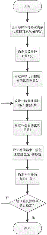
[0055] The specific implementation of the present invention will be described below with reference to the accompanying drawings and by taking the LCL type grid-connected inverter as an example, so that those skilled in the art can better understand the present invention.

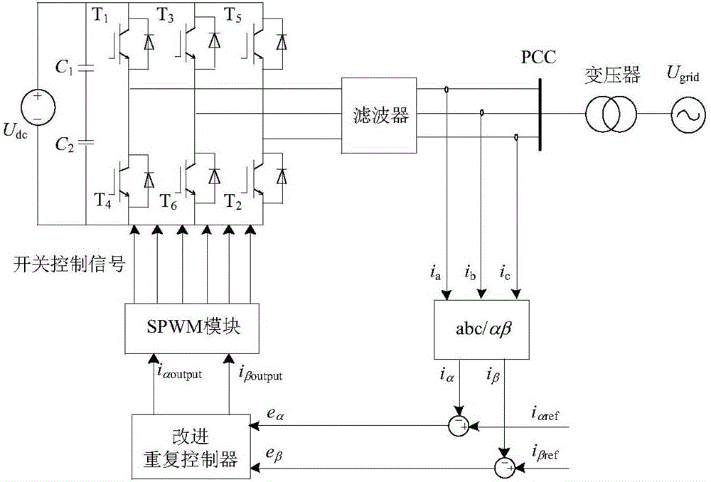
[0056] In this embodiment, the grid-connected inverter mainly includes two parts, a main circuit and a control circuit.

[0057] The main circuit includes: DC voltage source, three-phase half-bridge inverter circuit and LCL filter. Among them, the DC voltage U dc =400V; Inverter side inductance L in LCL filter 1 =0.3mH, grid side inductance L 2 =1mH, filter capacitor C=100μF, damping resistance R=1Ω on the capacitor branch; the three-phase half-bridge inverter circuit is connected to the common connection point through the LCL filter, and then connected to the external power grid through the step-up transformer.

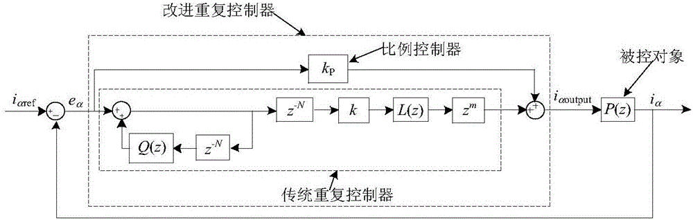
[0058] The control circuit includes: abc / αβ coordinate system transformation module, improve...


PUM


Abstract

The invention belongs to the technical field of grid-connection, control and protection of distributed type energy resources, and relates to a design method of improving a repetitive controller applied to grid-connected inverter current control. The method comprises the steps of determining a controlled object P (s) of a grid-connected inverter current control loop; determining the control feedback quantity of the grid-connected inverter current control loop; calculating an error signal under grid-connected inverter current control; determining and improving a repetitive controller structure; designing parameters for improving the repetitive controller, wherein the step comprises the procedures of designing a parallel-connection proportional controller proportionality coefficient Kp, a first-order low-pass filter Q (z) parameter, a compensator proportionality coefficient k, a second-order low-pass filter L (z) parameter and an m value of an advancing link zm. According to the design method of improving the repetitive controller applied to the grid-connected inverter current control, fast and precise tracking of a grid-connected inverter output current to a reference current can be achieved.

Description

technical field [0001] The invention relates to an improved repetitive controller design method applied to the current control of a grid-connected inverter. Background technique [0002] Grid-connected inverter current control technology is one of the key technologies of grid-connected inverter. Common grid-connected inverter current control methods include proportional-integral (PI) control method and proportional resonant (PR) control method. The proportional-integral control method can realize fast and precise tracking of the DC reference current; the proportional resonance control method can realize fast and precise tracking of the reference current at a specific frequency. However, in some applications, such as using the remaining capacity of the grid-connected inverter for harmonic compensation, the type and content of harmonics contained in the reference current will be significantly increased. At this time, neither the proportional integral control method nor the pr...

Claims


Application Information

Patent Timeline
Patent Type & Authority Applications(China)
IPC IPC(8): H02M7/5387
CPCH02M7/53871
Inventor 李永丽卜立之靳伟孙广宇
Owner TIANJIN UNIV
Why Eureka
Try Eureka