
Permanent magnet synchronous motor speed regulation control method based on self-adaptive terminal sliding mode

A permanent magnet synchronous motor and self-adaptive terminal technology, which is applied in the direction of motor generator control, AC motor control, electronic commutation motor control, etc., can solve the problem that linear PI control is difficult to meet the control requirements, and achieve improvement difficult to measure and weaken Chattering, effects of improving convergence performance

Active Publication Date: 2020-12-29
苏州富斯源智能科技有限公司
View PDF5 Cites 0 Cited by
  • Summary
  • Abstract
  • Description
  • Claims
  • Application Information

AI Technical Summary

Problems solved by technology

However, the permanent magnet synchronous motor is a time-varying and complex nonlinear system, and the traditional linear PI control is difficult to meet its control requirements in practical applications.

Method used


Image

  • Permanent magnet synchronous motor speed regulation control method based on self-adaptive terminal sliding mode
  • Permanent magnet synchronous motor speed regulation control method based on self-adaptive terminal sliding mode
  • Permanent magnet synchronous motor speed regulation control method based on self-adaptive terminal sliding mode

Examples


Embodiment Construction

[0049] The present invention will be further described below in conjunction with accompanying drawing.

[0050] The invention discloses an adaptive terminal sliding mode control method, which is used for the speed regulation control of a permanent magnet synchronous motor. In order to make the purpose, technical solutions and beneficial effects of the present invention more clear and definite, the present invention will be further elaborated below through the accompanying drawings and research examples.

[0051] figure 1 It is a vector control block diagram of a permanent magnet synchronous motor of the present invention, which includes: (1) a permanent magnet synchronous motor module; (2) a speed loop module; (3) two current loop modules; (4) a coordinate transformation module; (5) SVPWM module; (6) inverter module.

[0052] Based on the above-mentioned control system, the present invention explains the speed regulation control method of the permanent magnet synchronous mot...


PUM


Abstract

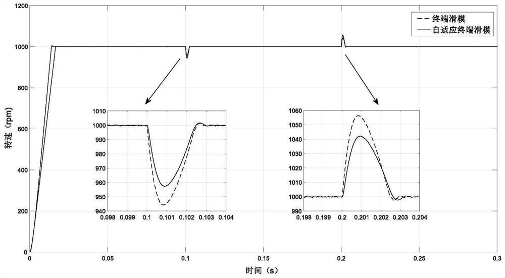
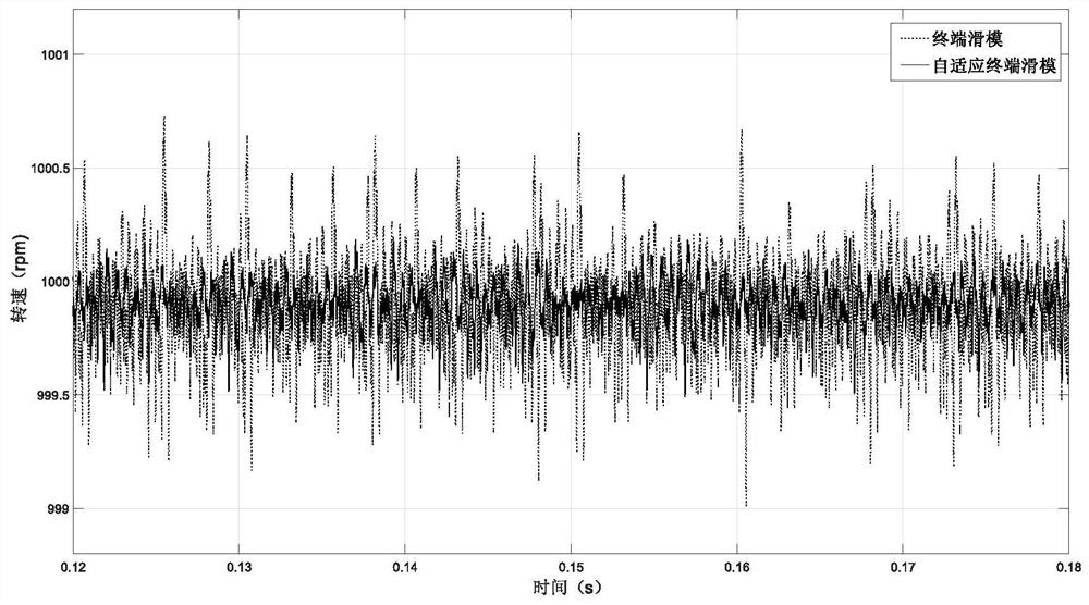
The invention discloses a permanent magnet synchronous motor speed regulation control method based on a self-adaptive terminal sliding mode. The method comprises the steps: firstly, establishing a kinetic equation describing the relation between q-axis current and speed output omega of a permanent magnet synchronous motor stator; designing a permanent magnet synchronous motor speed loop controllerby using a terminal sliding mode control algorithm; then, according to a sliding mode control theory, establishing a relationship between system disturbance and control gain, and estimating an average value of high-frequency switching signals by using a differential observer; and finally, designing a self-adaptive law to optimize the switching gain. The method has the advantages that the designedsliding mode surface effectively avoids the singular phenomenon of the system at the balance point, and the convergence performance of the system is improved through introduction of nonlinear terms;the differential observer is used for estimating the average value of the high-frequency switching signals, and the problem that the high-frequency switching signals are difficult to measure in actualworking conditions is solved; the designed self-adaptive law enables the terminal sliding mode controller to select a proper switching gain according to the magnitude of disturbance, significantly weakens the buffeting of the system, and enhances the anti-interference performance of the system.

Description

technical field [0001] The invention relates to the technical field of speed regulation control of permanent magnet synchronous motors, in particular to a speed regulation control method of permanent magnet synchronous motors based on an adaptive terminal sliding mode. Background technique [0002] Due to its small size, simple structure, small moment of inertia, and high efficiency, permanent magnet synchronous motors are widely used in robotics, aerospace, and industrial automation. In recent years, due to the rapid development of power electronics technology, microelectronics technology and rare earth permanent magnet materials, permanent magnet synchronous motors have been widely used in practical engineering. However, the permanent magnet synchronous motor is a time-varying and complex nonlinear system, and the traditional linear PI control is difficult to meet its control requirements in practical applications. [0003] In order to improve the control performance of t...

Claims


Application Information

Patent Timeline
Patent Type & Authority Applications(China)
IPC IPC(8): H02P21/00H02P21/13H02P21/14H02P21/05H02P25/022
CPCH02P21/0007H02P21/0017H02P21/13H02P21/14H02P21/05H02P25/022
Inventor 丁世宏王婷婷后乾康马莉
Owner 苏州富斯源智能科技有限公司
Learn More