Control system for optimum frequency conversion point of photon and operation method thereof

A control system and frequency conversion point technology, applied in transmission systems, electromagnetic wave transmission systems, optical fiber transmission, etc., can solve problems affecting the power and phase stability of frequency conversion output signals

Active Publication Date: 2017-05-31
NO 34 RES INST OF CHINA ELECTRONICS TECH GRP +2
View PDF5 Cites 0 Cited by
  • Summary
  • Abstract
  • Description
  • Claims
  • Application Information

AI Technical Summary

Problems solved by technology

[0005] However, optical domain frequency conversion devices are very sensitive to environmental changes such as external temperature, stress, and humidity, and their optimal frequency conversion point will show irregular and rapid changes due to the influence of the external environment, thereby affecting the power and phase stability of the frequency conversion output signal

Method used


Image

  • Control system for optimum frequency conversion point of photon and operation method thereof
  • Control system for optimum frequency conversion point of photon and operation method thereof
  • Control system for optimum frequency conversion point of photon and operation method thereof

Examples


Embodiment Construction

[0059] Embodiment of photon optimal frequency conversion point control system

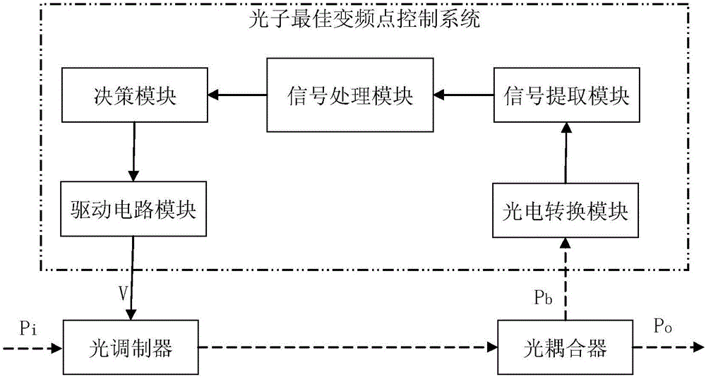
[0060] The structural block diagram of the photon optimal frequency conversion point control system embodiment is as follows figure 1 As shown, it includes a photoelectric conversion module, a signal extraction module, a signal processing module, a decision module and a driving circuit module connected in sequence. In the figure, arrows with dotted lines indicate optical signals, and arrows with solid lines indicate electrical signals. Optical signal P i After frequency conversion by the optical modulator, it is connected to the optical coupler, and the optical coupler couples a part of the optical signal into the output fiber as the optical output P o , the other part as the return signal P b Connect to the photoelectric conversion module of the photon optimal frequency conversion point control system. The photoelectric conversion module converts the incoming optical signal into a correspondin...


PUM


Abstract

The invention relates to a control system for optimum frequency conversion point of a photon and the operation method thereof. The control system for optimum frequency conversion point of a photon is characterized by comprises the following steps: a part of the frequency converted light output of the light modulator is sent to the photovoltaic conversion module of the system as the return signals; the converted electrical signals enter the signal processing module through the signal extraction module; the electronically controlled signals is obtained through operations; and the control voltage is output to the light modulator through the decision module and the drive circuit module. The operation method comprises the following steps: initializing firstly; reading the electrical signals converted by the photoelectric conversion module, which is carried out by the signal extraction module; sending to the information processing module after preprocessing; performing curve fitting circularly on the signals; performing differential, integral and scaling operations to obtain the real time electronic control signals; outputting the control voltage to the light modulator through the decision module and the drive circuit module; and making the light modulator work at the optimum frequency conversion point. The hardware of the system disclosed by the invention realizes the rapid and precise control of the light modulator to work at the optimum frequency conversion point, therefore, the frequency of the outputting optical signals is stable, the dynamic range of the upper and lower frequency conversion of the frequency conversion of the photon is increased, the transmission loss is reduced, and the electromagnetic interference is also prevented.

Description

technical field [0001] The invention relates to the technical field of microwave frequency conversion, in particular to a photon optimal frequency conversion point control system and an operating method thereof, so as to realize traditional up-down frequency conversion of microwave signals in the optical domain. Background technique [0002] Microwave frequency conversion is widely used. In the fields of communication, technical investigation, spectrum monitoring, electronic countermeasures, remote sensing and control, etc., it is necessary to down-convert the received signal to an intermediate frequency for processing when receiving the signal, and to up-convert the intermediate frequency signal when transmitting. For radio frequency signals to transmit. [0003] In the microwave / RF circuits of traditional frequency conversion system transmitters and receivers, the up-conversion and down-conversion of microwave frequencies are generally realized by using diode mixers and ac...

Claims


Application Information

Patent Timeline
Patent Type & Authority Applications(China)
IPC IPC(8): H04B10/556H04B10/2575
CPCH04B10/2575H04B10/5563
Inventor 代丰羽朱少林臧习飞陈协助尹怡辉王俊郎
Owner NO 34 RES INST OF CHINA ELECTRONICS TECH GRP
Why Eureka
Try Eureka