LED driving circuit compatible to different types of ballast

A LED drive and ballast technology, applied in the field of LED drive, can solve problems such as heavy workload

Inactive Publication Date: 2017-05-31
浙江东元照明有限公司
View PDF5 Cites 1 Cited by
  • Summary
  • Abstract
  • Description
  • Claims
  • Application Information

AI Technical Summary

Problems solved by technology

[0003] With the application of LED technology, more and more energy-saving fluorescent tubes (PL tubes) are replaced by LED tubes, but the problem that follows is that the electronic ballasts or inductive ballasts set before In the circuit or embedded in the wall, the LED lamp replaces the energy-saving fluorescent lamp with a large workload

Method used


Image

  • LED driving circuit compatible to different types of ballast
  • LED driving circuit compatible to different types of ballast

Examples


Embodiment Construction

[0026] In order to make the purpose, technical solutions and advantages of the embodiments of the present invention clearer, the technical solutions in the embodiments of the present invention will be clearly and completely described below in conjunction with the drawings in the embodiments of the present invention. Obviously, the described embodiments It is only some embodiments of the present invention, but not all embodiments.

[0027] Based on the embodiments of the present invention, all other embodiments obtained by persons of ordinary skill in the art without making creative efforts belong to the protection scope of the present invention.

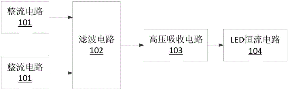
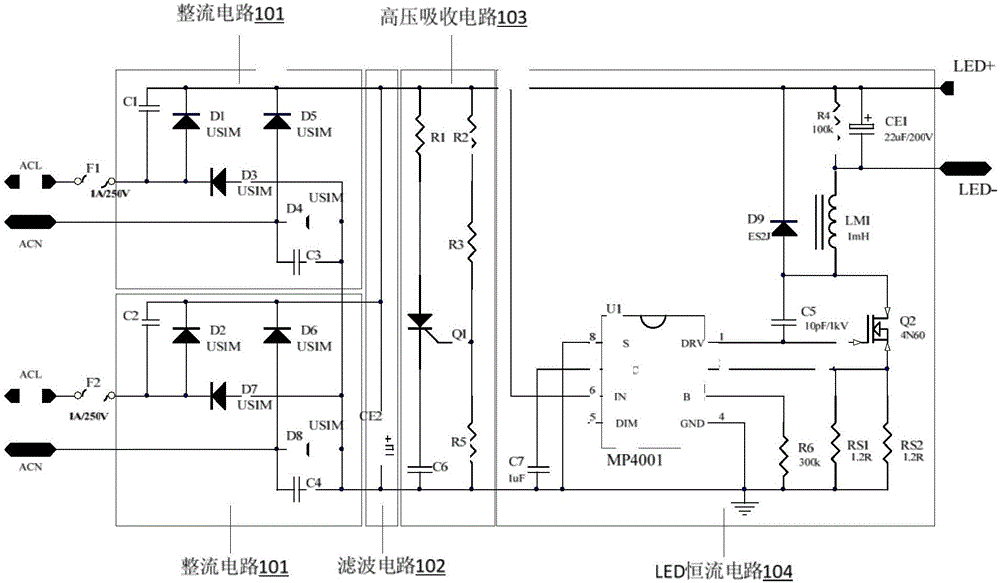
[0028] see figure 1 and figure 2 , an LED drive circuit compatible with various ballasts provided by an embodiment of the present invention includes a two-way rectifier circuit 101, a filter circuit 102, a high voltage absorbing circuit 103 and an LED constant current circuit 104, wherein the filter circuit 102, the high voltage ab...


PUM


Abstract

An embodiment of the invention discloses an LED driving circuit compatible to different types of ballast. The LED driving circuit comprises two rectification circuits, a filter circuit, a high-voltage absorption circuit and an LED constant-current circuit. The filter circuit, the high-voltage absorption circuit and the LED constant-current circuit are sequentially arranged at output ends of the rectification circuits in a parallel connection manner, input ends of the filter circuit, the high-voltage absorption circuit and the LED constant-current circuit are connected with the output ends of the rectification circuits, and the rectification circuits are used for rectifying output or AC input of the electronic ballast and the inductance ballast; the filter circuit is used for filtering output of the rectification circuits; the high-voltage absorption circuit is used for absorbing high voltages when the high voltages are outputted by the electronic ballast; the LED constant-current circuit is used for providing constant-current voltages required when LED load works.

Description

technical field [0001] The invention relates to the technical field of LED driving, in particular to an LED driving circuit compatible with various ballasts. Background technique [0002] Electronic ballast refers to electronic equipment that uses electronic technology to drive electric light sources to produce the required lighting. Corresponding to it is an inductive ballast (or ballast). More and more modern fluorescent lamps use electronic ballasts, which are light and compact, and can even integrate electronic ballasts with lamp tubes. Go for the starter alone. Electronic ballasts can also have more functions, such as improving or eliminating the flickering phenomenon of fluorescent lamps by increasing the current frequency or current waveform (such as becoming a square wave); it is also possible to use DC power for fluorescent lamps through the power inverter process. Some disadvantages of the traditional inductive rectifier make it being replaced by increasingly ma...

Claims


Application Information

Patent Timeline
Patent Type & Authority Applications(China)
IPC IPC(8): H05B33/08H05B44/00
CPCH05B45/37H05B45/00
Inventor 柯建锋
Owner 浙江东元照明有限公司
Why Eureka
Try Eureka