A Rotatable Inductively Coupled Loop Structure of a Superconducting Cyclotron Resonator

A cyclotron, inductive coupling technology, applied in magnetic resonance accelerators, electrical components, accelerators, etc., can solve the problems of reducing work efficiency, unable to find the best adjustable coupling matching point, slow progress, etc., to improve work efficiency Effect

Active Publication Date: 2018-02-02
HEFEI CAS ION MEDICAL & TECHNICAL DEVICES CO LTD
View PDF5 Cites 0 Cited by
  • Summary
  • Abstract
  • Description
  • Claims
  • Application Information

AI Technical Summary

Problems solved by technology

However, for the current inductive coupling ring coupling method, it is impossible to find the best adjustable coupling matching position point during the running and debugging process, which makes the whole progress slow and seriously reduces work efficiency.

Method used


Image

  • A Rotatable Inductively Coupled Loop Structure of a Superconducting Cyclotron Resonator
  • A Rotatable Inductively Coupled Loop Structure of a Superconducting Cyclotron Resonator

Examples


Embodiment Construction

[0022] The following will clearly and completely describe the technical solutions in the embodiments of the present invention with reference to the accompanying drawings in the embodiments of the present invention. Obviously, the described embodiments are only some, not all, embodiments of the present invention. Based on the embodiments of the present invention, all other embodiments obtained by persons of ordinary skill in the art without creative efforts fall within the protection scope of the present invention.

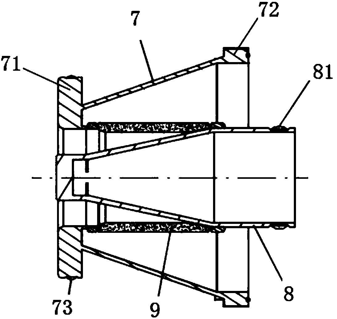
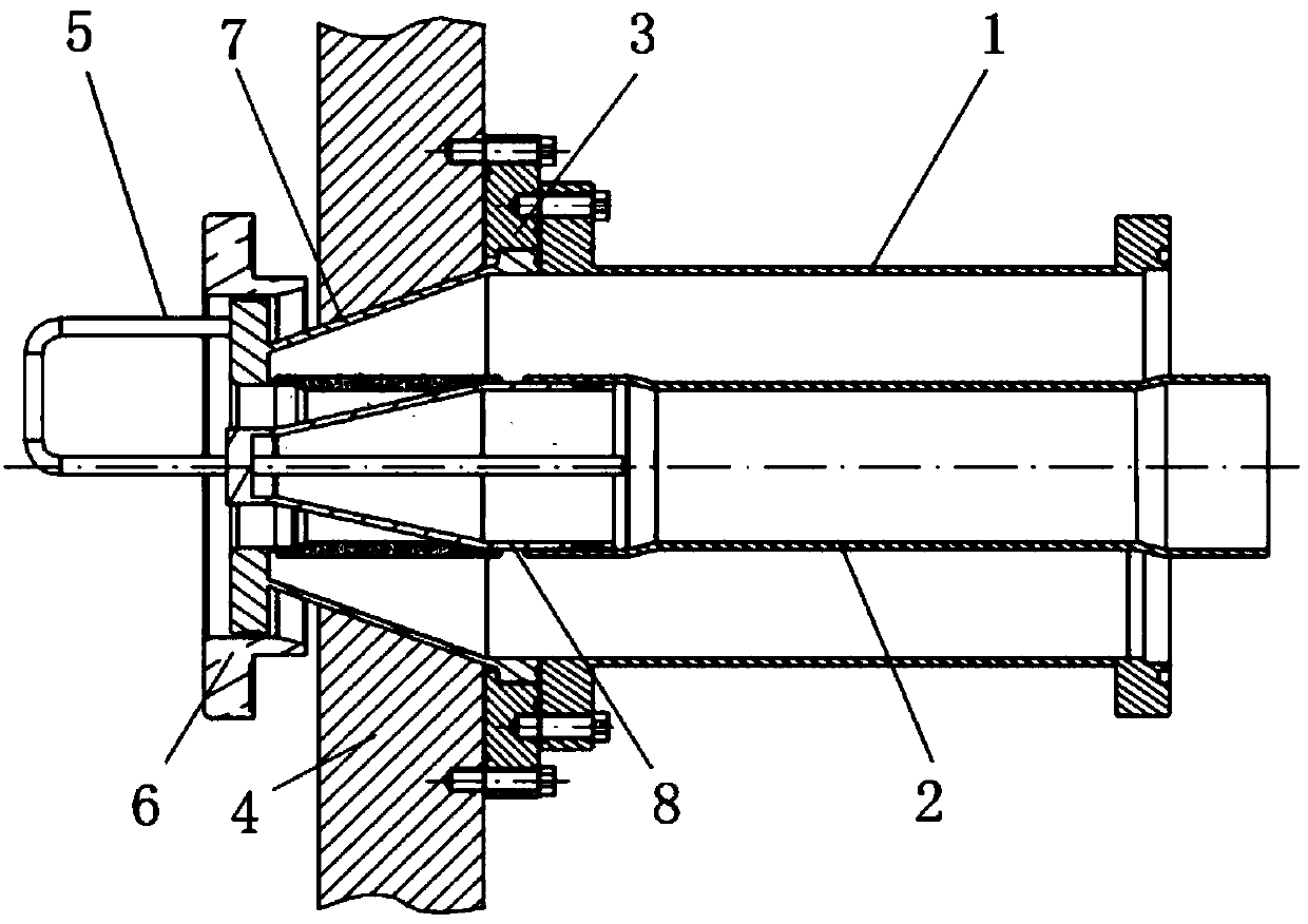
[0023] see figure 1 , a superconducting cyclotron resonant cavity rotatable inductive coupling ring structure, comprising an outer conductor 7, a fixed ring 9, an inner conductor 8 and a coupling ring 5;

[0024] The outer conductor 7 is tapered and annular, the front end of the outer conductor 7 is a limiting ring 71, and the rear end of the outer conductor 7 is a connecting ring 72;

[0025] The fixed ring 9 is coaxially arranged in the outer conductor 7, and th...


PUM


Abstract

The invention discloses a resonant cavity rotatable inductive coupling ring structure of a superconducting rotary accelerator. The inductive coupling ring structure comprises an outer conductor, a fixing ring, an inner conductor and a coupling ring, wherein the outer conductor is in a conical annular shape; the front end of the outer conductor is provided with a position limiting ring; the rear end of the outer conductor is provided with a connecting ring; the fixing ring is coaxially arranged in the outer conductor; the front end of the fixing ring is connected with an inner end opening of the position limiting ring; the front end of the inner conductor is provided with a conical ring; the rear end of the inner conductor is provided with a round ring coaxially connected with the conical ring; the inner conductor is arranged in the fixing ring; the end head of the conical ring at the front end of the inner conductor is positioned at an outer end opening part of the position limiting ring; the outer ring surface of the round ring at the rear end is connected with the inner wall of the rear end of the fixing ring; the front end of the coupling ring is in a U-shaped rod shape; the rear end of the coupling ring is in a straight rod shape; a straight rod arranged at the rear end of the coupling rind is coaxially and fixedly connected in the inner conductor; a U-shaped rod arranged at the front end of the coupling ring is positioned at the outer side of the position limiting ring. The inductive coupling ring structure has the advantages that the coupling ring magnetic flux change is changed through rotation; the maximum coupling power is realized; the work efficiency of the whole process is improved.

Description

technical field [0001] The invention belongs to the technical field of an isochronous superconducting cyclotron, and in particular relates to a rotating inductive coupling ring structure of a resonant cavity of a superconducting cyclotron. Background technique [0002] The main function of the cyclotron is to accelerate protons to high energy by using high-frequency electric field under the guidance of magnetic field. With the development of interdisciplinary subjects, cyclotrons are playing an increasingly important role in the fields of nuclear medicine, astrophysics, material science, energy, biology, and industrial processing. [0003] Cyclotron is a multi-professional comprehensive interdisciplinary subject, which involves accelerator physics and many high-tech fields, including radio frequency, electromagnetic field, power supply, vacuum, precision machinery, electronics and so on. Among them, the high-frequency system is an important system of the particle cyclotron,...

Claims


Application Information

Patent Timeline
Patent Type & Authority Patents(China)
IPC IPC(8): H05H13/00H05H7/00
CPCH05H7/00H05H13/005
Inventor 宋云涛杨庆喜王永胜陈根张鑫
Owner HEFEI CAS ION MEDICAL & TECHNICAL DEVICES CO LTD
Why Eureka
Try Eureka