
Imaging device and endoscope device

A camera device, endoscope technology, applied to endoscopes, installations, telescopes, etc., can solve problems such as reducing height and size

Inactive Publication Date: 2017-05-31
OLYMPUS CORP
View PDF7 Cites 2 Cited by
  • Summary
  • Abstract
  • Description
  • Claims
  • Application Information

AI Technical Summary

Problems solved by technology

[0003] Generally, an imaging device used for an endoscope or the like utilizes a metal frame member to hold the outer peripheral portion of the lens group as the objective optical system, and regulates the positions of the radial direction and the optical axis direction of the lens group, but as the insertion portion is thinned The technology that discloses a kind of imaging device for endoscope (for example, refer to patent document 1 and 2), this imaging device for endoscope is provided with the interval of optical path direction on the member that the frame member of objective lens optical system is held, And after cutting off the outer peripheral surface of the space part, it is arranged close to the upper surface side of the solid-state imaging element, thereby reducing the height dimension

Method used


Image

  • Imaging device and endoscope device
  • Imaging device and endoscope device
  • Imaging device and endoscope device

Examples


Embodiment Construction

[0034] In the following description, an endoscope device having a camera module will be described as a mode for carrying out the present invention (hereinafter referred to as "embodiment"). Moreover, this invention is not limited to this embodiment. In addition, in the description of the drawings, the same reference numerals are assigned to the same parts. In addition, the drawings are schematic, and it should be noted that the relationship between the thickness and width of each member, the ratio of each member, and the like are different from actual ones. In addition, between the drawings, there are also parts with different dimensions and ratios.

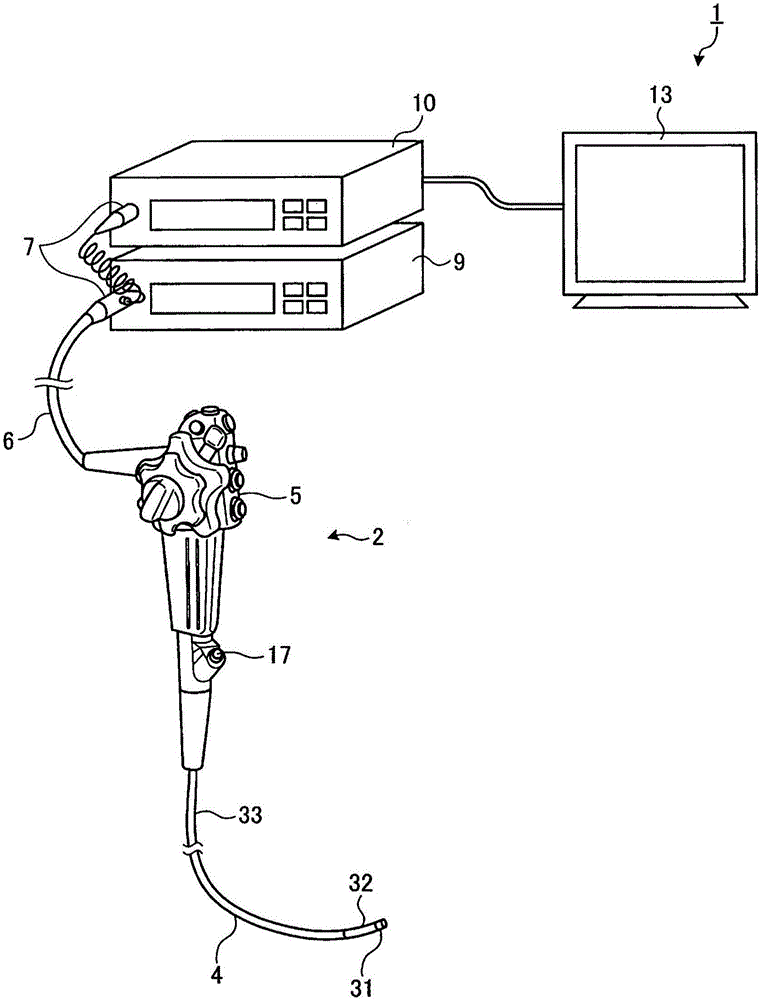
[0035] figure 1 It is a diagram schematically showing the overall configuration of an endoscope system according to an embodiment of the present invention. Such as figure 1 As shown, the endoscope device 1 has an endoscope 2 , a universal cable 6 , a connector 7 , a light source device 9 , a processor (control device) 10 , an...


PUM


Abstract

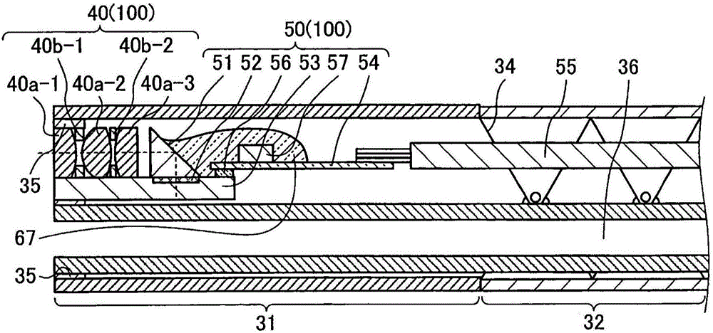
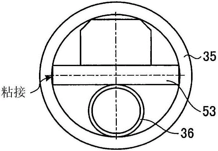
Provided are a miniaturizable imaging device and an endoscope device. The imaging device (100) is characterized by being provided with: objective lenses (40a-1 to 40a-3) that gather incoming light; a prism (51) that reflects the light gathered by the objective lenses (40a-1 to 40a-3); and an imaging element (53) having a light reception unit (52) that generates an electric signal by receiving the light reflected by the prism (51) and performing photoelectric conversion. The imaging device (100) is further characterized in that the prism (51) is mounted above the light reception unit (52), and the objective lenses (40a-1 to 40a-3) are directly mounted to the surface of the imaging element (53).

Description

technical field [0001] The present invention relates to an imaging device installed at the tip of an insertion portion of an endoscope inserted into a subject to image a site to be examined, and an endoscope device using the imaging device. Background technique [0002] Conventionally, endoscope devices have been widely used for various inspections in the medical and industrial fields. Among them, a medical endoscope device can observe a subject site by inserting a flexible and slender insertion part with an imaging device built into the distal end into the body cavity of a subject such as a patient. Ease of introduction into the subject requires a reduction in the diameter of the insertion portion. [0003] Generally, an imaging device used for an endoscope or the like utilizes a metal frame member to hold the outer peripheral portion of the lens group as the objective optical system, and regulates the positions of the radial direction and the optical axis direction of the...

Claims


Application Information

Patent Timeline
Patent Type & Authority Applications(China)
IPC IPC(8): A61B1/00A61B1/04G02B7/00G02B23/24G02B23/26
CPCG02B23/2423G02B23/2469G02B27/62A61B1/00096A61B1/051G02B23/02G02B23/243H04N23/555A61B1/00163H04N23/56A61B1/05
Inventor 藤森纪幸
Owner OLYMPUS CORP
Learn More