Pellicle, pellicle production method and exposure method using pellicle
A technology of a protective film assembly and a manufacturing method, applied in the field of exposure
- Summary
- Abstract
- Description
- Claims
- Application Information
AI Technical Summary
Problems solved by technology
Method used
Image

Examples
Embodiment approach 1
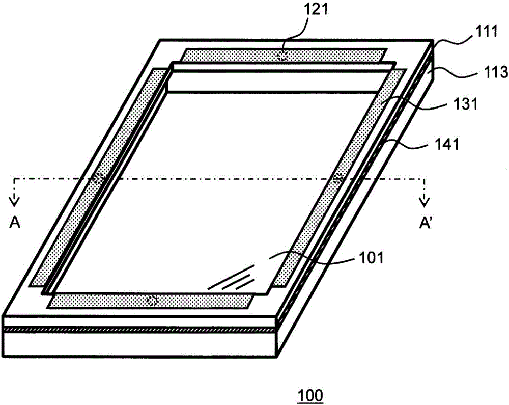
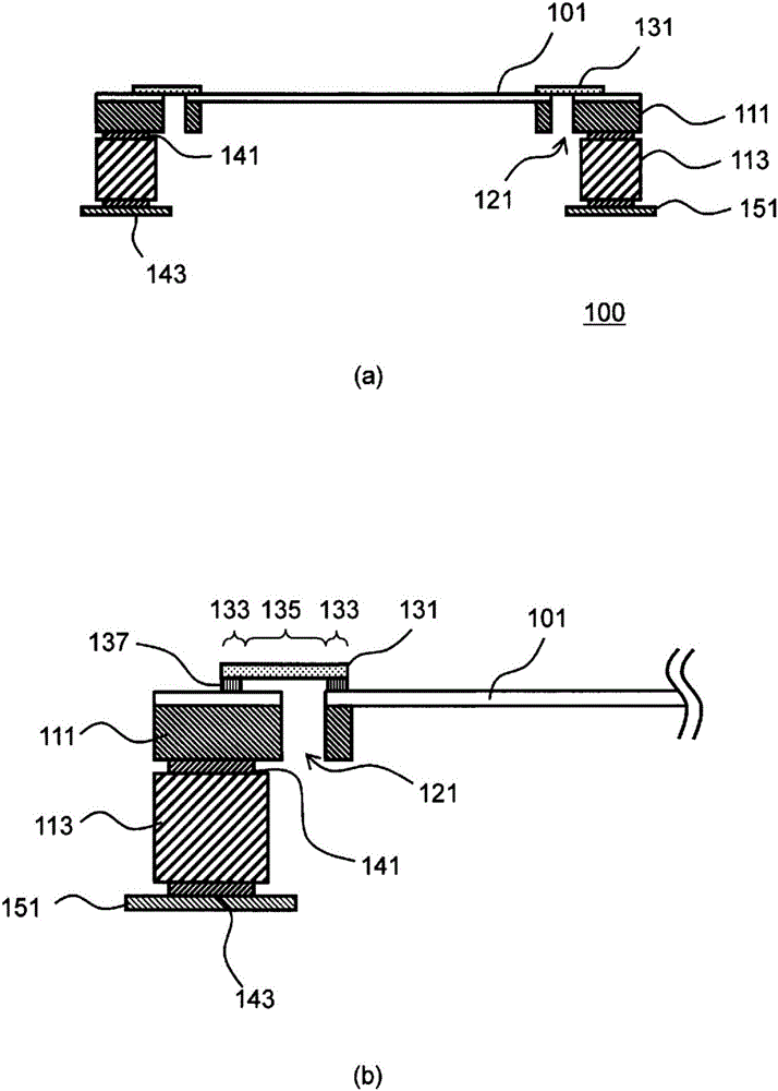
[0094] figure 1 It is a schematic diagram (perspective view) of a pellicle module 100 according to an embodiment of the present invention. figure 2 is a pellicle assembly of 100 figure 1 Section view at the line segment AA' of . figure 2 (a) is the pellicle assembly 100 figure 1 The profile at the line segment AA' of figure 2 (b) is figure 2 (a) Partial enlarged view. The pellicle module 100 includes a first frame 111 on which the pellicle 101 is arranged, and a second frame 113 that supports the first frame 111 . In addition, the pellicle module 100 includes a through hole 121 through which the pellicle 101 and the first frame body 111 pass through, and a filter 131 arranged on the pellicle 101 and covering the through hole 121 ( figure 2 (a)). The filter 131 is arranged on the area of the pellicle 101 on the first frame body 111 through the adhesive layer 137 ( figure 2 (b)). in addition, figure 2 Although the second frame body 113 is provided on the surfa...
Embodiment approach 2
[0129] In the pellicle module 100 of Embodiment 1, since the through-hole 121 is arranged inside the second frame body 113 , it is necessary to make the width of the first frame body 111 larger than the width of the second frame body 113 . As described above, when the pellicle is placed on a photomask, the width of the first frame affects the aperture ratio of the pellicle. In this embodiment, an example in which a through-hole is arranged while reducing the width of the first housing will be described.
[0130] Figure 5 of the pellicle module 200 according to one embodiment of the present invention figure 1Section view at the line segment AA' of . The pellicle module 200 includes a first frame 211 on which the pellicle 201 is arranged, and a second frame 213 that supports the first frame 211 . Furthermore, the pellicle module 200 includes a through hole 221 penetrating the pellicle 201 and the first frame body 211 , and a filter 231 arranged on the pellicle 201 to cover t...
Embodiment approach 3
[0155] As a modified example of Embodiment 2, the pellicle module 300 of Embodiment 3 will be described. Figure 8 of the pellicle module 300 according to one embodiment of the present invention figure 1 Section view at the line segment AA' of . The pellicle module 300 of the third embodiment is different from the pellicle module 200 of the second embodiment in that the groove 325 of the first frame body 311 is etched to the position where it contacts the pellicle 301, and the through hole 321 is formed. The holes 323 are of equal height. The other configurations are the same as those of the pellicle module 200, and therefore detailed descriptions are omitted.
[0156]In the pellicle module 300, the through-hole 321 passes through the pellicle 301 and the first frame 311 to form a hole 323 through which the groove 325 of the first frame 311 is directly connected to the second frame 313, so the air permeability is greatly improved.
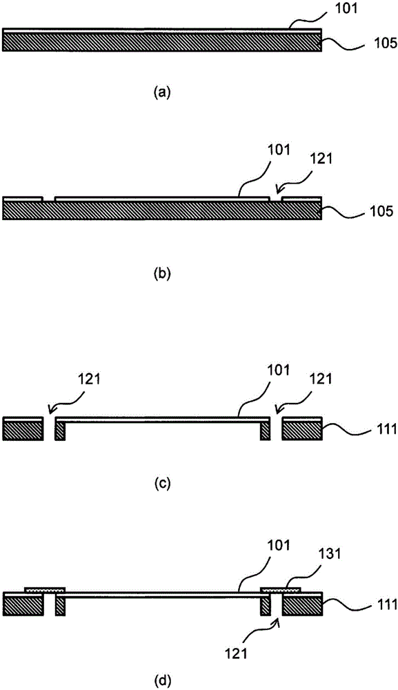
[0157] (Manufacturing method of pellicle ...
PUM
| Property | Measurement | Unit |
|---|---|---|
| thickness | aaaaa | aaaaa |
| height | aaaaa | aaaaa |
| thickness | aaaaa | aaaaa |
Abstract
Description
Claims
Application Information
 - R&D Engineer
- R&D Manager
- IP Professional
- Industry Leading Data Capabilities
- Powerful AI technology
- Patent DNA Extraction
Browse by: Latest US Patents, China's latest patents, Technical Efficacy Thesaurus, Application Domain, Technology Topic.
© 2024 PatSnap. All rights reserved.Legal|Privacy policy|Modern Slavery Act Transparency Statement|Sitemap