On-site repair machining process of lower labyrinth ring of rotating wheel

A processing technology and labyrinth ring technology, which is applied in the field of on-site repair processing technology and assembly of the lower labyrinth ring, can solve the problems of slow project progress, long repair cycle, low efficiency, etc., and achieves reduction of processing cost, short repair cycle and high efficiency. Effect

Active Publication Date: 2017-06-06
GUANGZHOU XINCHENG MECHANICAL TECH
View PDF7 Cites 3 Cited by
  • Summary
  • Abstract
  • Description
  • Claims
  • Application Information

AI Technical Summary

Problems solved by technology

[0003] According to the traditional repairing and processing method, it is necessary to use a super-large vertical lathe to transport the runner to the large processing equipment for repair, and then transport it back to the designated place for installation. A lot of manpower, material and financial resources; In addition, the traditional repair method also has the following shortcomings:
[0004] 1. Using super-large machine tools to process super-large parts, the cost of machine tool purchase and installation is very high;
[0005] 2. After the processing is completed, the parts may not be able to be transported, or the transportation cost is high, and the transportation risk is high;
[0006] 3. The repair period is long, resulting in slow project progress and low efficiency

Method used


Image

  • On-site repair machining process of lower labyrinth ring of rotating wheel
  • On-site repair machining process of lower labyrinth ring of rotating wheel
  • On-site repair machining process of lower labyrinth ring of rotating wheel

Examples


Embodiment 1

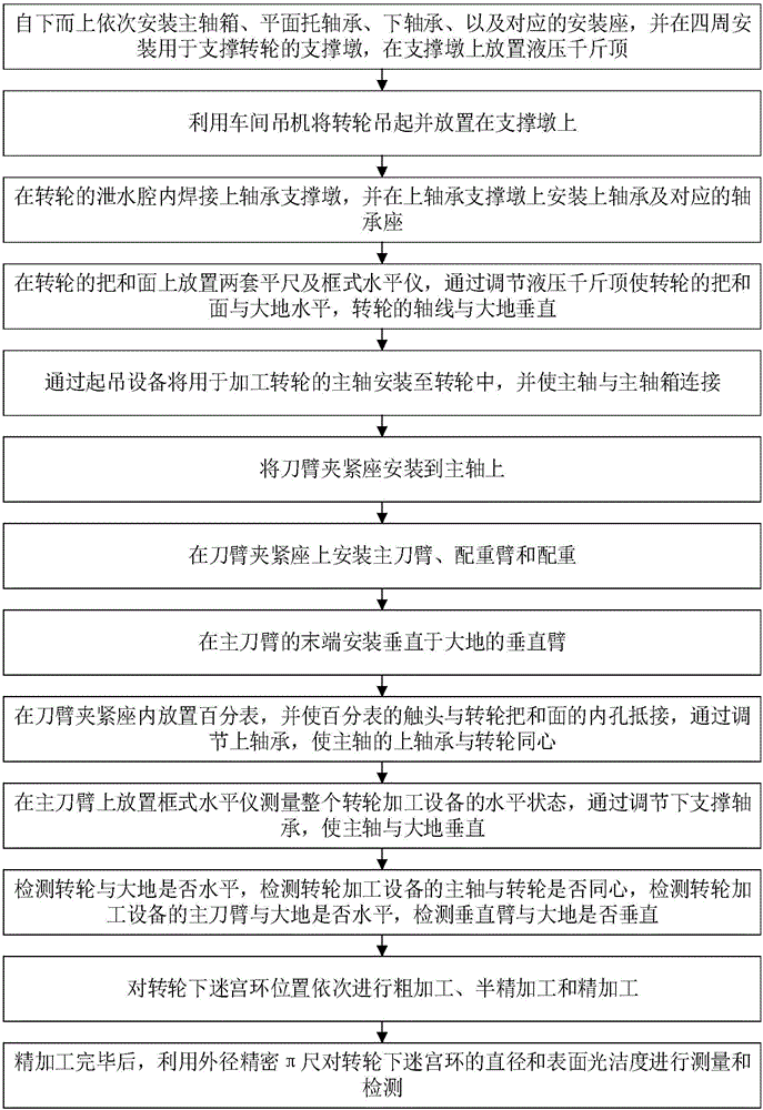
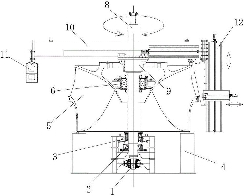
[0048] like figure 1 and figure 2 As shown, the present invention discloses a process for on-site repairing of a labyrinth ring under a runner. The process mainly includes the following steps:

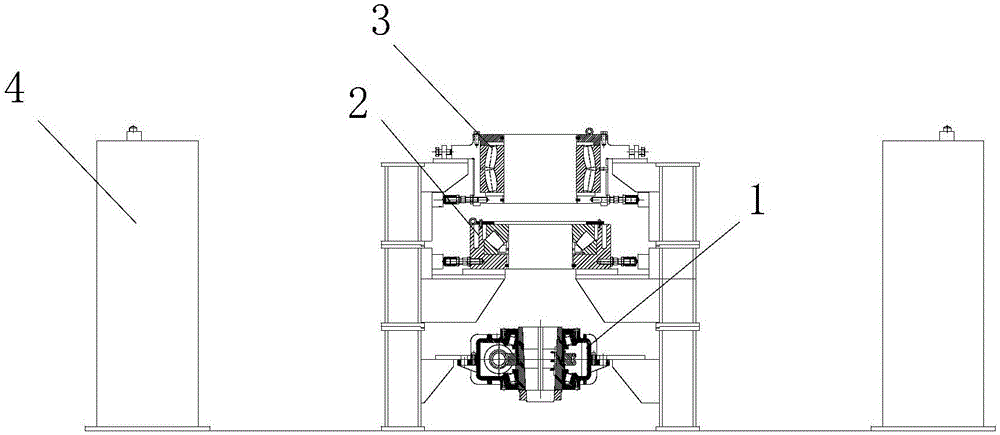
[0049] Step S1: if image 3 As shown, install the headstock 1, the plane support bearing 2, the lower bearing 3, and the corresponding mounting seat in sequence from bottom to top, and install the supporting pier 4 for supporting the runner 5 around, and place the hydraulic pressure on the supporting pier 4. jack.

[0050] The main shaft box 1 is used as a power device to drive the main shaft 8 to rotate; the plane support bearing 2 mainly supports the weight of the entire processing equipment, making the runner processing equipment more stable and more stable; the lower bearing 3 is mainly used for the main shaft 8 is positioned and centered so that the main shaft 8 is perpendicular to the earth and on the centerline of the runner 5. The main shaft box 1, the plane support bearin...


PUM


Abstract

The invention discloses an on-site repair machining process of a lower labyrinth ring of a rotating wheel. The process comprises the following steps of firstly, installing a main shaft box, a plane supporting bearing, a lower bearing and a supporting pier on the ground, and installing a jack on the supporting pier; secondly, placing the rotating wheel on the jack, and keeping the rotating wheel parallel to the horizontal plane; thirdly, installing an upper bearing in a water draining cavity of the rotating wheel, installing a main shaft in the rotating wheel, connecting the main shaft to the main shaft box, adjusting the upper bearing, and ensuring that the upper bearing is concentric with the rotating wheel; fourthly, installing a tool arm clamping base, a main tool arm and a balance weight on the main shaft, installing a perpendicular arm on the main tool arm, adjusting the lower bearing, ensuring that the main shaft is perpendicular to the horizontal plane, enabling the main tool arm to be parallel to the horizontal plane, and enabling the perpendicular arm to be perpendicular to the horizontal plane; fifthly, carrying out rough machining, semi-finish machining and finish machining on the position of the lower labyrinth ring; and sixthly, detecting the outer diameter and the surface smoothness of the lower labyrinth ring and evaluating the machining effect. The on-site repair machining process is simple to operate, low in repair cost, short in machining period, high in efficiency and good in effect.

Description

technical field [0001] The invention relates to the technical field of on-site repair of large parts, in particular to an on-site repair process and assembly method for a lower labyrinth ring of an upper runner of a hydropower station. Background technique [0002] For some hydropower stations set up by rivers with relatively high silt content (such as the Yellow River), the runners are impacted by silt during operation, which will cause serious wear and tear on the labyrinth ring under the runners over time. Therefore, after the hydropower station has been in operation for a period of time, it is necessary to repair and repair the entire circle of the lower labyrinth ring. [0003] According to the traditional repairing and processing method, it is necessary to use a super-large vertical lathe to transport the runner to the large processing equipment for repair, and then transport it back to the designated place for installation. A lot of manpower, material and financial r...

Claims


Application Information

Patent Timeline
Patent Type & Authority Applications(China)
IPC IPC(8): B23P6/00F03B11/00
CPCB23P6/00F03B11/006Y02E10/20Y02P70/50
Inventor 张国根
Owner GUANGZHOU XINCHENG MECHANICAL TECH
Why Eureka
Try Eureka