Fixator

A technology for a fixer and a locking assembly, applied in the field of fixators, can solve the problems of complex structure, unreliable fixation, laborious operation, etc. of the fixer, and achieve the effects of simple structure, reliable fixation and convenient use.

Active Publication Date: 2017-06-06
浙江宇钻精密元件有限公司
View PDF7 Cites 3 Cited by
  • Summary
  • Abstract
  • Description
  • Claims
  • Application Information

AI Technical Summary

Problems solved by technology

Especially in the case of high motion precision requirements, such as high-precision turntables, it is necessary to strictly protect the motion contact parts. If the moving

Method used


Image

  • Fixator
  • Fixator

Examples


Embodiment Construction

[0020] In order to make the object, technical solution and advantages of the present invention clearer, the present invention will be further described in detail below in conjunction with the accompanying drawings.

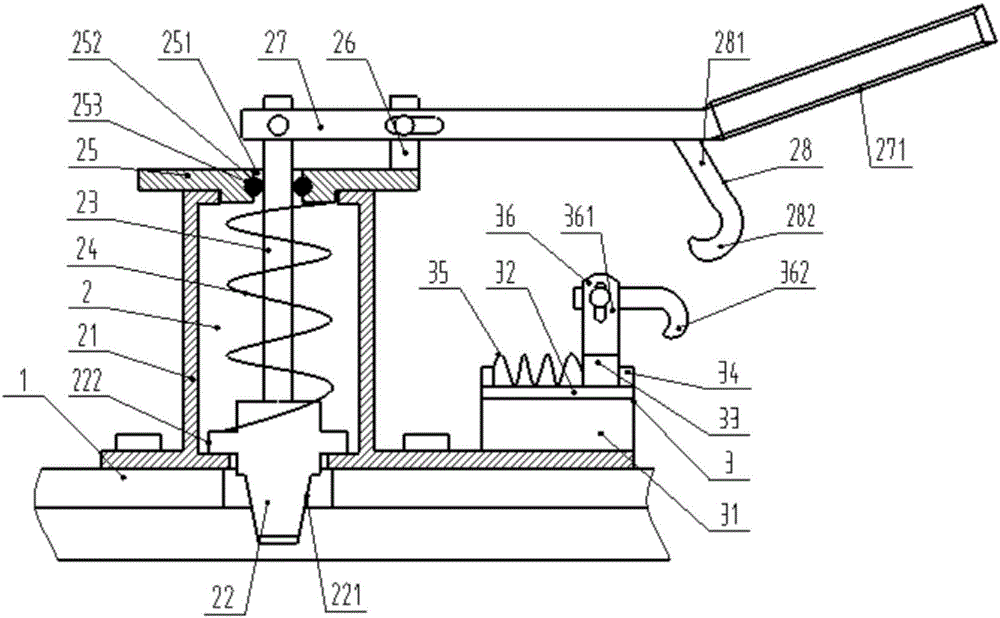
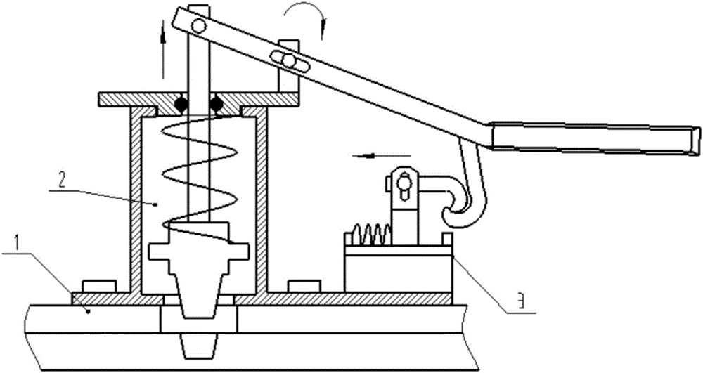
[0021] like Figure 1-2 As shown, it includes a mounting base 1, a locking assembly 2 and a buckle assembly 3 provided on the mounting base. The locking assembly includes a sleeve 21, a lock tongue 22 inside the sleeve, a connecting rod 23 connected to the tail end of the lock tongue, and a sleeve. The elastic member 24 connected to the connecting rod, the cover plate 25 detachably connected to the upper end of the sleeve, the projection 26 arranged on the upper surface of the cover plate and the handle located at the tail end of the connecting rod; the front end of the deadbolt can extend to the sleeve Outside the lower end, the cover plate has a through hole 251 through which the connecting rod passes. One end of the elastic member is connected to the rear end o...


PUM


Abstract

The invention discloses a fixator. The fixator comprises a mounting base as well as a locking assembly and a buckling assembly which are arranged on the mounting base, wherein the locking cylinder comprises a sleeve, a lock tongue which is sleeved by the sleeve, a connecting rod which is connected with the tail end of the lock tongue, an elastic part which sleeves the connecting rod, a cover plate which is detachably connected to the upper end of the sleeve, a bump which is arranged on the upper surface of the cover plate, and a handle which is arranged at the tail end of the connecting rod; the buckling assembly comprises a supporting base, a guide rail arranged on the supporting base, a slide block arranged on the guide rail, baffle plates which are arranged at the two ends of the guide rail, a spring which is connected between the slide block and the baffle plate at one side, and a lock body which is arranged on the slide block for fixing a buckle body. According to the fixator disclosed by the invention, the front section of the handle body is rotatably connected with the tail end of the connecting rod and the bump; when the handle is rotated, the handle body rotates around the bump and drives the connecting rod to perform lifting motion; when the handle is loosened, the lock tongue extends out of the sleeve under action of elastic force of the elastic part for fixing; and when the handle is downwards pressed, the lock tongue is driven by the connecting rod to upwards slide into the sleeve, so that the functional needs of fixing and loosening the fixator are effectively realized.

Description

technical field [0001] The invention relates to the technical field of mountable and detachable fixing machines, in particular to a fixing device. Background technique [0002] In many mechanical products, it involves the structural design problem that the moving unit and the static unit need to be fixed. For example, mobile platforms, sliding guide rails or turntables, when the moving parts need to be structurally fixed after the movement is completed, in order to prevent the moving parts from slipping without human control due to their own gravity or other external forces, resulting in unforeseen circumstances. Predicted component damage and damage, resulting in related safety accidents. Especially in the case of high motion accuracy requirements, such as high-precision turntables, the motion contact parts need to be strictly protected. If the moving parts shift or slide, the motion accuracy will be seriously affected. However, the structure of the existing fixture is rel...

Claims


Application Information

Patent Timeline
IPC IPC(8): F16B1/04
CPCF16B1/04
Inventor 石宪云
Owner 浙江宇钻精密元件有限公司
Why Eureka
Try Eureka