Composite air-cooling pipe finned heat exchanger structure

A heat exchanger and tube-fin type technology is applied in the field of composite air-cooled tube-fin heat exchanger structures to achieve a balance between cost and heat transfer performance, small wind side resistance, and ease of cost and heat transfer performance. Effect

Inactive Publication Date: 2017-06-06
TONGFANG ARTIFICIAL ENVIRONMENT
View PDF5 Cites 5 Cited by
  • Summary
  • Abstract
  • Description
  • Claims
  • Application Information

AI Technical Summary

Problems solved by technology

It can effectively overcome the problems of uneven wind speed, large change of refrigerant flow rate in the pipe, and large resistance to wind exchange with small pipe diameter, and significantly improve the comprehensive performance of the air heat exchanger, thereby optimizing the performance of the air source heat pump.

Method used


Image

  • Composite air-cooling pipe finned heat exchanger structure
  • Composite air-cooling pipe finned heat exchanger structure
  • Composite air-cooling pipe finned heat exchanger structure

Examples


Embodiment approach 1

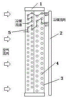
[0025] see image 3 and Figure 4 , is a schematic diagram of two sub-air heat exchangers 3 connected in series, and the number of rows of copper tubes 4 in the sub-air heat exchanger 3 is two rows. The refrigerant channel passes through the copper tubes 4 with large and small diameters in sequence.

[0026] Under cooling conditions, the refrigerant flows out from the header 2 and first passes through the channel with a large pipe diameter. The refrigerant is in gaseous state, and the flow velocity decreases under the large pipe diameter. As condensation progresses, the specific volume of the refrigerant decreases. In the second half, the refrigerant enters the channel with a small diameter. At this time, due to the reduction of the cross-sectional area of ​​the channel, the flow rate of the refrigerant will not be greatly reduced, thereby ensuring a certain flow rate in the tube and ensuring the heat exchange effect.

[0027] Under the heating condition, the flow direction...

Embodiment approach 2

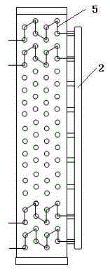
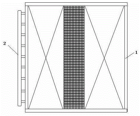
[0030] see Figure 5 , is a schematic diagram of two sub-air heat exchangers 3 connected in parallel, and the number of rows of copper tubes 4 in each sub-air heat exchanger 3 is also different. The sub-air heat exchanger 3 below adopts a large pipe diameter and a two-row structure, and the air side resistance of the sub-air heat exchanger 3 is relatively small. The blower fan 6 is located at the top and is in the form of an upper air outlet.

[0031] For the form of upper air outlet, because the upper and lower structures of the traditional heat exchanger are consistent, the wind speed difference between the upper part and the lower part of the heat exchanger is relatively large, and the wind speed in the lower part is lower than that in the upper part, especially for the wind heat exchanger with V-shaped structure. As a result, the lower heat exchange area is not fully utilized, which affects the overall heat exchange effect. In the combined wind heat exchanger with parall...

Embodiment approach 3

[0034] see Image 6 , is a schematic diagram of three sub-air heat exchangers 3 connected in series, the number of rows of sub-air heat exchangers 3 is 1 row, and the heights of different sub-air heat exchangers 3 are inconsistent. The refrigerant channel passes through copper tubes 4 with three diameters of large, medium and small in sequence.

[0035] Compared with Embodiment 1, this structure has more sub-air heat exchangers 3, more diameter changes in the refrigerant channel, and a better consistency between the change of refrigerant flow rate and the change of refrigerant specific volume, so the resistance of the refrigerant and the heat transfer The balance effect is better. Moreover, because the fins have more discontinuities, the flow of air is more turbulent, which is beneficial to improve the heat exchange effect of the air side. The difference from Embodiment 1 is that the heights of the three air heat exchangers 3 in this structure are inconsistent, and the actua...


PUM


Abstract

A composite air-cooling pipe finned heat exchanger structure relates to the technical field of air conditioning refrigeration and comprises a heat exchanger set formed by two or more sub-air heat exchangers in serial and parallel connection or a serial-parallel connection combined way. Copper tubes and fins in each sub-air heat exchangers are independent to each other; the tube diameters of the copper tubes of each sub-air heat exchangers are different; the sub-air heat exchangers in the heat exchanger arranged in a serial-connection structure are orderly arrayed according to the sizes of the tube diameters of the copper tubes; the sub-air heat exchangers of the heat exchanger arranged in the parallel-connection structure are orderly arrayed according to the size of air-side resistance; each cold medium flow paths of the heat exchanger arranged in the parallel-connection structure only flow through the same sub-air heat exchanger; each cold medium flow path of the heat exchanger arranged in the serial or parallel-connection structures or the serial-parallel mixing structure orderly flows through each sub-air heat exchanger. Problems of unevenness of wind speed, great change of intra-tube refrigerant flowing speed and great air exchanging resistance of small tube diameter can be overcome; and comprehensive performance of the air heat exchanger can be obviously improved, so performance of an air source heat pump can be optimized.

Description

technical field [0001] The invention relates to the technical field of air conditioning and refrigeration, in particular to the structure of a composite air-cooled tube-fin heat exchanger. Background technique [0002] With the development of urbanization and the improvement of people's living standards, the demand for heating is increasing in both quantity and quality. However, the traditional heating method using boilers as heat sources has problems such as low energy efficiency, heavy pollution, and difficult regulation. Clean and energy-saving air source heat pump units have gradually attracted attention and favor in recent years. [0003] Compared with traditional boilers, air source heat pump units are not only clean and energy-saving, have no direct discharge of pollutants, have high energy efficiency, and are dual-purpose for heating and cooling, which can save initial investment. In addition, it also has the advantages of convenient installation and use, and flexib...

Claims


Application Information

Patent Timeline
Patent Type & Authority Applications(China)
IPC IPC(8): F25B39/00
Inventor 韩林俊
Owner TONGFANG ARTIFICIAL ENVIRONMENT
Why Eureka
Try Eureka