Apparatus For Deriving Natural Frequency Of Cutting Tool

A technology of inherent vibration and cutting tools, applied in manufacturing tools, measuring devices, program control, etc., can solve the problems of poor machining accuracy and surface accuracy.

Inactive Publication Date: 2017-06-06
DMG MORI CO LTD
View PDF2 Cites 4 Cited by
  • Summary
  • Abstract
  • Description
  • Claims
  • Application Information

AI Technical Summary

Problems solved by technology

[0002] Currently, when machining workpieces with machine tools, machining accuracy (especially surface accuracy) deteriorates due to chatter

Method used


Image

  • Apparatus For Deriving Natural Frequency Of Cutting Tool
  • Apparatus For Deriving Natural Frequency Of Cutting Tool
  • Apparatus For Deriving Natural Frequency Of Cutting Tool

Examples


Embodiment Construction

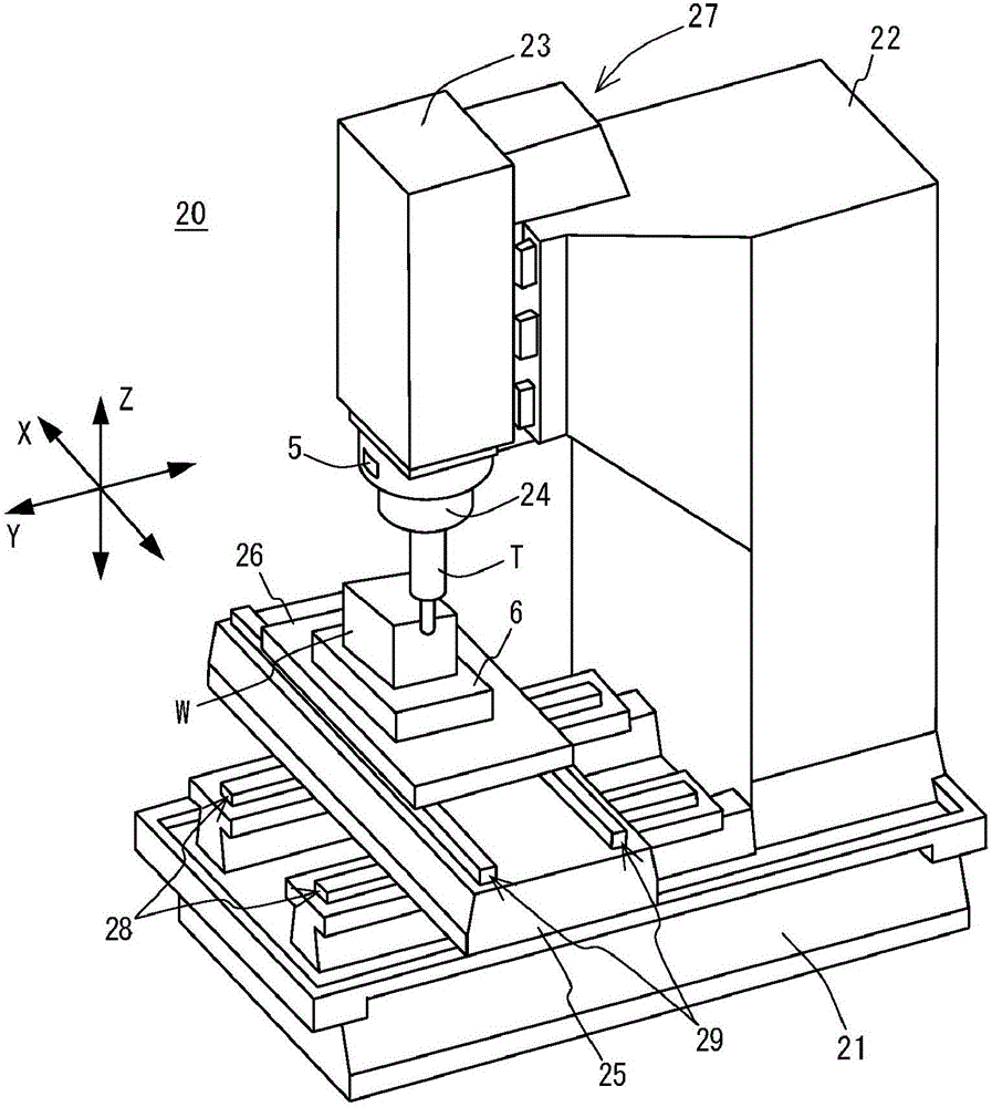
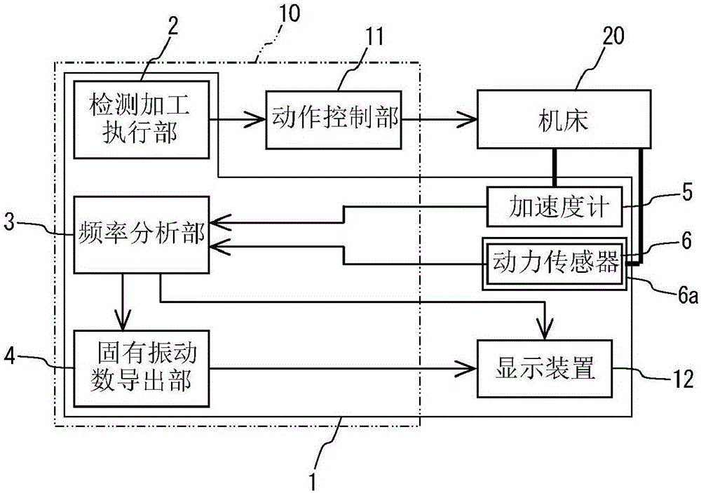
[0074] Hereinafter, specific embodiments of the present invention will be described with reference to the drawings. figure 1 is a perspective view showing a machine tool used in this embodiment, figure 2 It is a block diagram showing the natural frequency derivation device and the like of the present embodiment.

[0075] [Outline configuration of machine tool]

[0076]First, the schematic configuration of the machine tool 20 will be described. This machine tool 20 is provided with: a base (bed) 21; a column 22, which is erected on the base 21; surface); the main shaft 24 is freely rotatably held on the main shaft head 23 along the shaft center; On the base 21; the workbench 26 is freely movable on the saddle 25 in the X-axis direction shown by the arrow; the X-axis feed mechanism 29 makes the workbench 26 move on the X-axis (the first axis) ) direction; the Y-axis feed mechanism 28 makes the saddle 25 move in the direction of the Y-axis (second axis); the Z-axis feed mech...


PUM


Abstract

An apparatus includes a machining executing part causing a machine tool to execute an operation of, while changing a spindle rotation speed of the machine tool in a stepwise manner, machining a workpiece by a predetermined distance or for a predetermined period of time at each spindle rotation speed, a displacement detector detecting a position displacement of a tool during the machining, a cutting force detector detecting a cutting force applied to the tool, a frequency analysis part performing frequency analysis on displacement data and cutting force data for each rotation speed to calculate a displacement spectrum and a cutting force spectrum, and a natural frequency deriving part calculating a compliance spectrum for each spindle rotation speed by deriving the displacement spectrum by the cutting force spectrum, calculating an integrated compliance spectrum by superimposing the compliance spectra, and deriving, as a natural frequency, a frequency showing the largest compliance value.

Description

technical field [0001] The present invention relates to a method of deriving the natural vibration number of a cutting tool used when a workpiece (workpiece) is processed by a machine tool, a method of creating a stability limit curve for the regenerative vibration of the cutting tool, and the A device for deriving the natural vibration numbers of cutting tools. Background technique [0002] Currently, when a workpiece is machined using a machine tool, machining accuracy (especially surface accuracy) deteriorates due to chatter. This kind of flutter is roughly divided into forced flutter and self-excited flutter. It is generally believed that forced flutter is caused by excessive external force, or the frequency of the external force is synchronized with the resonance frequency of the vibration system. On the other hand, self-excited chatter includes regenerative chatter (regenerative chatter) and mode coupling (mode coupling) chatter. It is generally believed that regenera...

Claims


Application Information

Patent Timeline
Patent Type & Authority Applications(China)
IPC IPC(8): G06F17/50B23Q17/09B23Q17/22
CPCB23Q17/0952B23Q17/22G06F30/17B23Q11/0039B23Q17/0971G01N29/045G01N29/14G01N29/46G01M1/30B23Q11/0032B23Q17/0976B23Q17/12B23Q2717/00G05B19/401G01N29/449G01N2291/014
Inventor 河合谦吾大野胜彦西川静雄
Owner DMG MORI CO LTD
Why Eureka
Try Eureka