A mechanical arm transmission joint mechanism with force-position measurement function

A technology of transmission joints and mechanical arms, which is applied to manipulators, program-controlled manipulators, manufacturing tools, etc., can solve the problems of not considering the influence of the force position information of the transmission chain, the high price of high-performance force/torque sensors, and the inaccurate information. , to achieve the effect of large development space and application prospects, low cost and accurate measurement

Active Publication Date: 2020-02-21
HUAZHONG UNIV OF SCI & TECH
View PDF7 Cites 0 Cited by
  • Summary
  • Abstract
  • Description
  • Claims
  • Application Information

AI Technical Summary

Problems solved by technology

The former scheme only obtains the force / torque information at the end of the mechanical arm, the control scheme is complicated, the calculation is large, and the high-performance force / torque sensor is expensive and bulky; although the latter scheme can obtain the force position of each joint information, but the influence of the drive chain on the force position information is not considered, the obtained information is not accurate enough, and the error is large

Method used


Image

  • A mechanical arm transmission joint mechanism with force-position measurement function
  • A mechanical arm transmission joint mechanism with force-position measurement function
  • A mechanical arm transmission joint mechanism with force-position measurement function

Examples


Embodiment Construction

[0021] In order to make the object, technical solution and advantages of the present invention more clear, the present invention will be further described in detail below in conjunction with the accompanying drawings and embodiments. It should be understood that the specific embodiments described here are only used to explain the present invention, not to limit the present invention. In addition, the technical features involved in the various embodiments of the present invention described below can be combined with each other as long as they do not constitute a conflict with each other.

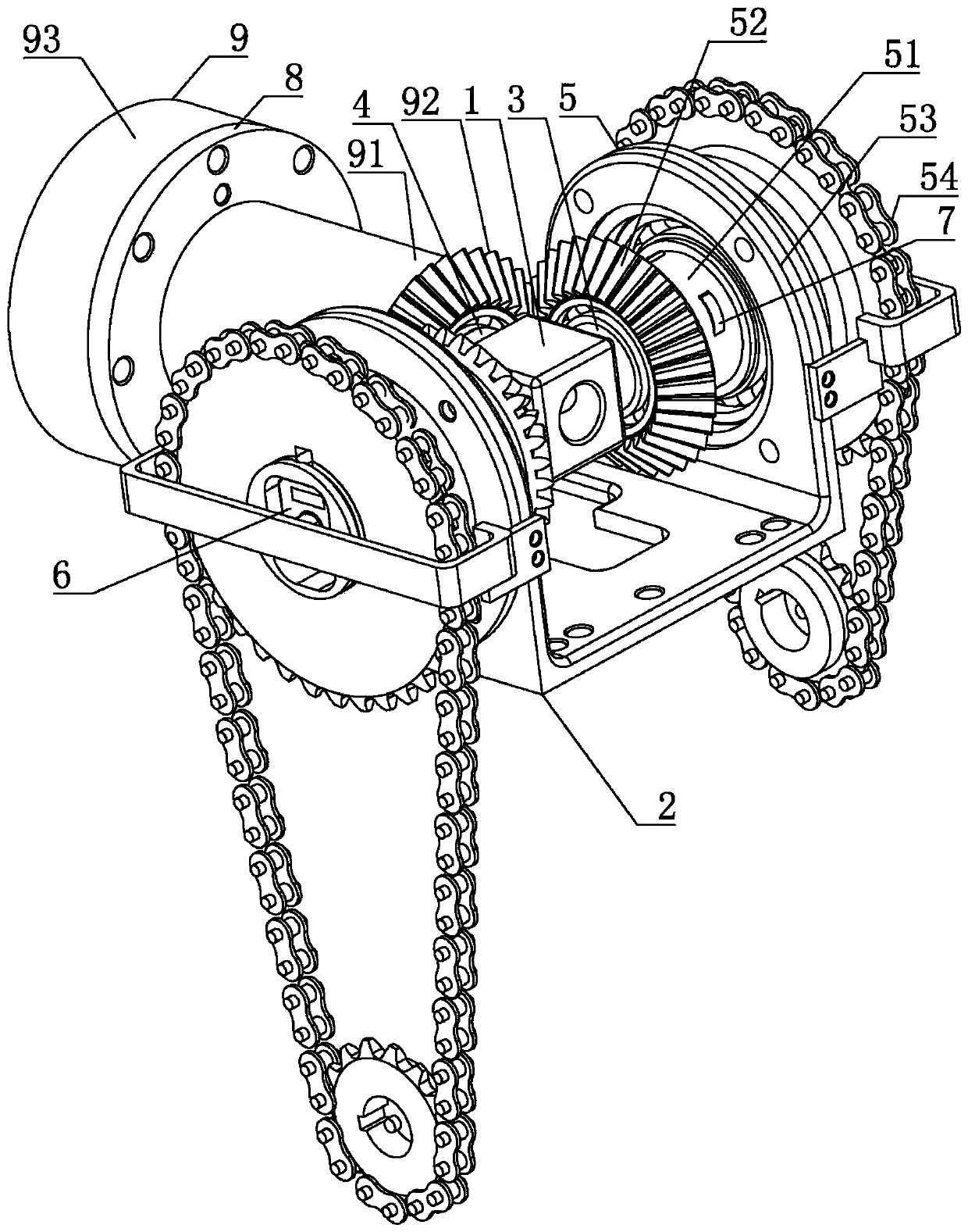
[0022] refer to Figure 1 ~ Figure 3 , a mechanical arm transmission joint mechanism with a force position measurement function, including a T-shaped gear frame 1 and a main bracket 2, wherein,

[0023] The T-shaped gear frame 1 has two first installation shafts 3 and a second installation shaft 4, the axes of the two first installation shafts 3 are co-linear, and the axis of the second inst...


PUM


Abstract

The invention belongs to the field of robot equipment, and discloses a mechanical arm transmission joint mechanism with a force-position measuring function. The mechanical arm transmission joint mechanism comprises a T-shaped gear frame and a main support, the T-shaped gear frame is provided with two first mounting shafts and a second mounting shafts, each of the first mounting shafts is provided with a power input mechanism, and the second mounting shaft is provided with a power output mechanism; the power input mechanism comprises a first sleeve-bevel gear composite body, a bearing base and a transmission device; the power output mechanism comprises a second sleeve and a second bevel gear; an inner cavity of the first sleeve is provided with an angle displacement sensor, and an inner ring of the angle displacement sensor is fixedly installed on the main support; the outer wall of each first sleeve is provided with multiple strain gauges used for measuring torque of the first sleeve in the circumstantial direction. According to the mechanical arm transmission joint mechanism with the force-position measuring function, by measuring the displacement and torque information of the two first sleeve respectively, the displacement and torque information of the second sleeve can be obtained through simple calculation, the cost is low, and the size is small and exquisite.

Description

technical field [0001] The invention belongs to the field of robot equipment, and more specifically relates to a mechanical arm transmission joint mechanism. Background technique [0002] The robotic arm is the most widely used automatic mechanical device in the field of robotics. It can be seen in industrial manufacturing, medical treatment, entertainment services, military, semiconductor manufacturing, and space exploration. With the development of technology, the man-machine collaboration performance of the manipulator has been widely valued by scholars at home and abroad. Arm its own influence, and change its behavior according to changes in the environment. For example, when the robotic arm hits the human arm, the robotic arm can sense the existence of the human arm based on the force sensor, and make timely actions to protect human safety, such as stopping and moving away. Therefore, how to improve the perception ability of the manipulator has become an important top...

Claims


Application Information

Patent Timeline
Patent Type & Authority Patents(China)
IPC IPC(8): B25J9/10
CPCB25J9/102
Inventor 熊蔡华何畅伍轩贺磊何立伟
Owner HUAZHONG UNIV OF SCI & TECH
Why Eureka
Try Eureka