Enclosed waterproof reinforced structure of original plain wall of shield and construction technology

A technology of strengthening structure and starting element, which is applied in the field of shield starting plain wall sealing water-stop reinforcement structure and construction technology, can solve the problems of long construction period and high cost of freezing method, achieve the purpose of strengthening the ground and blocking groundwater, and ensuring stability The effect of avoiding the dangerous situation of water gushing and sand gushing

Active Publication Date: 2017-06-09
CHINA RAILWAY SHISIJU GROUP CORP
View PDF9 Cites 5 Cited by
  • Summary
  • Abstract
  • Description
  • Claims
  • Application Information

AI Technical Summary

Problems solved by technology

In this invention, it is necessary to use the freezing method to strengthen the soil within 1-2m outside the door of the launching shaft, but the freezing method has a long construction period, high cost, and certain risks.

Method used


Image

  • Enclosed waterproof reinforced structure of original plain wall of shield and construction technology
  • Enclosed waterproof reinforced structure of original plain wall of shield and construction technology
  • Enclosed waterproof reinforced structure of original plain wall of shield and construction technology

Examples


Embodiment 1

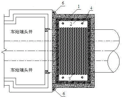
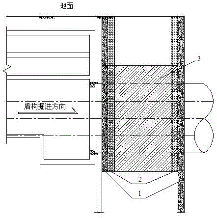
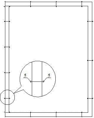
[0035] A shield water-stop reinforcement structure for the starting plain wall of the shield machine, the structure includes a mixing pile 3 arranged at the end of the shield starting shaft to reinforce the soil; Concrete underground diaphragm wall 1 forms a closed water-stop curtain structure with the enclosure wall of the station enclosure to reduce the influence of precipitation in the pit on the settlement of the soil outside the pit and ensure effective water isolation. The plain concrete underground diaphragm wall 1 The inner and outer sides of the joints are pre-embedded with grouting pipes 5, so as to perform grouting and anti-leakage operations on the joints with leakage; the plain concrete underground diaphragm wall 1 and the mixing pile 3 are closed with 2 rows of rotary grouting piles 2; More than one dewatering well 4 is also arranged in the reinforced area outside the tunnel diameter.

[0036] Stirring pile 3 adopts Φ850@600 three-axis stirring pile.

[0037] Th...

Embodiment 2

[0049] A shield water-stop reinforcement structure for the starting plain wall of the shield machine, the structure includes a mixing pile 3 arranged at the end of the shield starting shaft to reinforce the soil; Concrete underground diaphragm wall 1 forms a closed water-stop curtain structure with the enclosure wall of the station enclosure to reduce the influence of precipitation in the pit on the settlement of the soil outside the pit and ensure effective water isolation. To be safe, a concrete plain underground diaphragm wall 1 is set on the outer side of the enclosure wall of the station enclosure structure, the depth is 5m below the shield tunnel structure, and forms a closed connection with the "concave" plain concrete underground diaphragm wall 1 outside the reinforcement area of ​​the mixing pile 3. "Mouth" structure. Pre-embed the grouting pipes 5 inside and outside the joints of the plain concrete underground diaphragm wall 1, so as to perform grouting and anti-leak...


PUM


Abstract

The invention discloses an enclosed waterproof reinforced structure of an original plain wall of a shield and construction technology. The waterproof reinforced structure comprises underground continuous walls of C15 plain concrete (including pre-burying grouting pipes), two rows of rotary jet grouting pipes, three-axis mixing piles and many precipitation wells. The specification for the rotary jet grouting pipes is Phi800@500, and the specification for the three-axis mixing piles is Phi850@600. C15 plain underground continuous walls with embedding rocks of concave type are arranged on the periphery of the reinforced area, forming an enclosed waterproof curtain structure with underground continuous walls of station, then the sedimentation influencing ranges of the soil body outside the pits caused by precipitation inside the pits can be decreased and the effect of exclusion of water can be ensured effectively. Grouting pipes are pre-buried on both inner and outer sides of the underground continuous wall seams of the plain concrete, thereby achieving the operation of grouting and preventing leakage on the seams where leakage exists.

Description

technical field [0001] The invention relates to a sealing and water-stopping reinforcement structure and a construction process of a shield starting plain wall, and more particularly relates to a sealing water-stopping and strengthening structure and a construction process of a plain wall at the starting end of a large-diameter mud-water balance shield. Background technique [0002] Shield construction technology is widely used in the construction of urban subway tunnels in soil layers or weak surrounding rock strata, and is a very reliable tunnel construction technology. The shield starting technology is a very critical link in the shield tunneling construction technology system. Whether the shield starting is smooth or not is directly related to the quality of the later tunnel construction, the construction period and the safety of the construction process. [0003] In order to ensure the stability of the shield launching shaft, the end of the launching shaft needs to be r...

Claims


Application Information

Patent Timeline
Patent Type & Authority Applications(China)
IPC IPC(8): E21D11/10E21D11/38
CPCE21D11/105E21D11/38
Inventor 陈健王承震王德福商跃锋李义翔
Owner CHINA RAILWAY SHISIJU GROUP CORP
Why Eureka
Try Eureka