Laser toothbrush

A toothbrush and laser technology, used in dentistry, light therapy, cleaning teeth, etc., can solve the problems of gum disease that is easy to occur and difficult to heal, unable to remove pathogenic bacteria, and recurrent gum infection, so as to improve and treat gum disease, with simple structure, Easy-to-use effects

Inactive Publication Date: 2017-06-13
NO 34 RES INST OF CHINA ELECTRONICS TECH GRP +2
View PDF10 Cites 4 Cited by
  • Summary
  • Abstract
  • Description
  • Claims
  • Application Information

AI Technical Summary

Problems solved by technology

[0006] One of the main reasons why gum disease is easy to occur and difficult to heal is that the existing toothbrush, even an electric

Method used


Image

  • Laser toothbrush
  • Laser toothbrush
  • Laser toothbrush

Examples


Embodiment 1

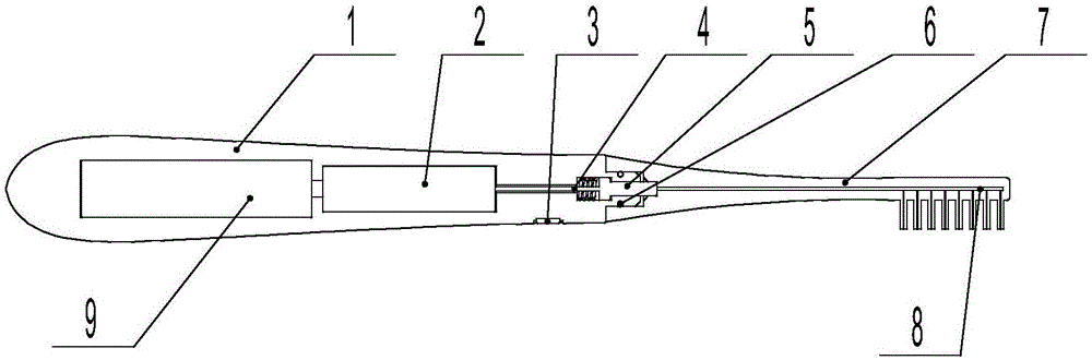
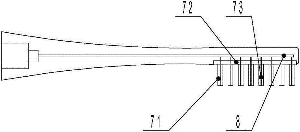
[0026] Embodiment 1 of this laser toothbrush is as figure 1 with 2 Shown, comprise brush handle 1 and brush head 7, brush head 7 contains bristle bundle 71 and bristle base plate 72, multituft bristle bundle 71 is planted on the bristle base plate 72, and laser device 2 and battery 9 are installed in brush handle 1, brush A laser switch 3 is arranged on the outer wall of the handle 1 . The butt ends of the brush handle 1 and the brush head 7 respectively have pluggable connectors 5 that cooperate with each other; The optical fiber 4 is connected to the optical fiber output end 8 in the bristle base plate 72 . The optical fiber output end 8 is connected with a plurality of optical fiber bristles 73 embedded in the bristle bundle 71 . After the brush head 7 is inserted into the brush handle 1 , the optical fiber 4 in the brush head 7 and the brush handle 1 is connected to each other through the connector 5 . The butt end of the brush handle 1 and the brush head 7 is equipped...

Embodiment 2

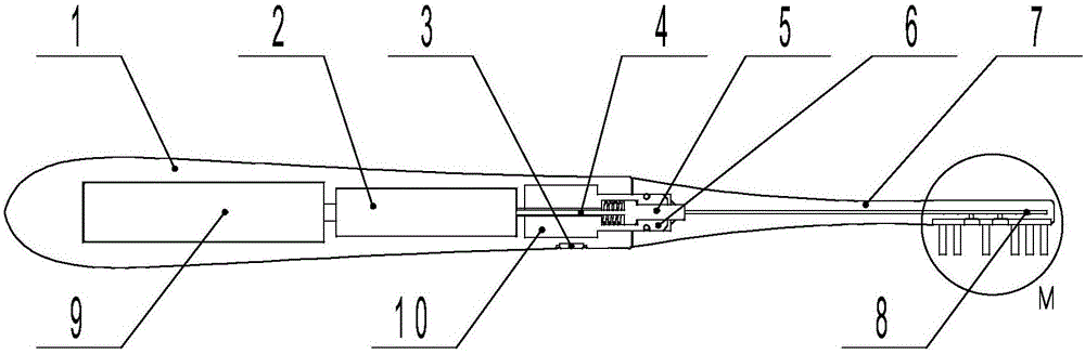
[0030] Embodiment 2 of this laser toothbrush is as image 3 with 4 Shown, comprise brush handle 1 and brush head 7, brush head 7 contains bristle bundle 71 and bristle base plate 72, multituft bristle bundle 71 is planted on the bristle base plate 72, and laser device 2 and battery 9 are installed in brush handle 1, brush A laser switch 3 is arranged on the outer wall of the handle 1 . The butt ends of the brush handle and the brush head have respectively mating pluggable connectors, the output end of the laser 2 is connected to the connector 5 at the butt end of the brush handle 1 through the optical fiber 4, and the connector 5 at the butt end of the brush head 7 is connected to the The optical fiber output end 8 in the bristle base plate is connected, and the optical fiber output end 8 of this example is connected to a plurality of lens barrels 74 embedded on the bristle base plate 72; the lens barrel 74 is embedded on the half of the bristle bundle 71 gap on the bristle b...


PUM

PropertyMeasurementUnit
Wavelengthaaaaaaaaaa

Abstract

The invention provides a laser toothbrush. A brush handle is internally provided with a laser device and a battery, wherein a laser device is mounted on an outer wall of the brush handle. Butt joint ends of the brush handle and a brush head are provided with connectors which are mutually matched; and an output end of the laser device is connected with an optical fiber output end in a bristle base plate through the brush handle and a brush head optical fiber connector. The optical fiber output end is connected with a plurality of optical fiber bristles planted into a bristle bundle or a plurality of lens cones which are embedded onto the bristle base plate. After the brush head and the brush handle are connected in an inserting manner, optical fibers in the brush head and the brush handle are mutually connected through the connectors. The wavelength of the laser device is 400nm-1000nm and the energy of laser beams is 0.5W-1.5W. The brush handle is internally provided with a motor; a transmission mechanism in the brush head is driven to rotate and/or vibrate through the connectors which are connected in the inserting manner, and the bristles move synchronously, so that the laser toothbrush is a laser electric toothbrush. When the toothbrush is used, laser reaches gaps between teeth and parts below gingiva lines in an oral cavity, so that bacteria in hidden parts of the oral cavity are effectively removed; and the laser toothbrush has the effect of lase treatment of dental department.

Description

technical field [0001] The invention relates to toothbrush design and manufacturing technology, in particular to a laser toothbrush. During the process of brushing teeth, the laser can also eliminate bacteria below the gum line in the oral cavity. Background technique [0002] Traditional toothbrushes are difficult to completely remove dental plaque, coupled with improper brushing methods, the cleaning effect of brushing is greatly reduced. Electric toothbrushes have a stronger cleaning ability than ordinary traditional toothbrushes. Statistics show that electric toothbrushes can remove 38% more plaque than ordinary manual toothbrushes. [0003] The electric toothbrush uses the rapid rotation or vibration of the motor in the handle to make the brush head rotate and / or generate high-frequency micro-vibration, which instantly breaks down the toothpaste into fine foam and cleans the teeth deeply; at the same time, the vibration of the bristles can promote blood circulation in t...

Claims


Application Information

Patent Timeline
IPC IPC(8): A61C17/26A61C17/34A61N5/067
CPCA61C17/26A61C17/34A61N5/0603A61N5/0624A61N2005/0606A61N2005/0644A61N5/067
Inventor 徐林马拥华安建欣雷利娟邓超邓婷甘润王琛
Owner NO 34 RES INST OF CHINA ELECTRONICS TECH GRP
Why Eureka
Try Eureka