Falling-film evaporation efficient gas and liquid mixer

A gas-liquid mixer, falling film evaporation technology, applied in the direction of evaporator liquid feeder, gas and gas/vapor mixing, evaporator accessories, etc., can solve the disadvantage of saving investment and maintenance costs, and low liquid heat exchange and gasification efficiency. , gas passing through the pressure drop and other problems, to ensure safe and reliable operation, easy automatic control, uniform gas-liquid mixing effect

Inactive Publication Date: 2017-06-13
JIANGSU DUBLE ENG
View PDF7 Cites 2 Cited by
  • Summary
  • Abstract
  • Description
  • Claims
  • Application Information

AI Technical Summary

Problems solved by technology

[0003] Existing gas-liquid mixing equipment generally has problems such as low liquid heat exchange and gasification efficiency, poor mixing uniformity, and large pressure drop throu

Method used


Image

  • Falling-film evaporation efficient gas and liquid mixer
  • Falling-film evaporation efficient gas and liquid mixer
  • Falling-film evaporation efficient gas and liquid mixer

Examples


Embodiment 1

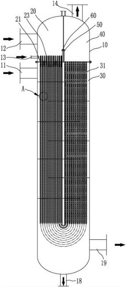
[0039] Such as Figure 1 to Figure 8 As shown, the falling film evaporation high-efficiency gas-liquid mixer includes a cylinder 10, and the cylinder 10 is divided into a feed chamber 20, a main evaporation mixing chamber 30 and a discharge chamber 40;

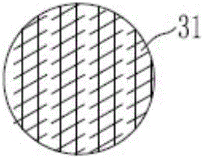
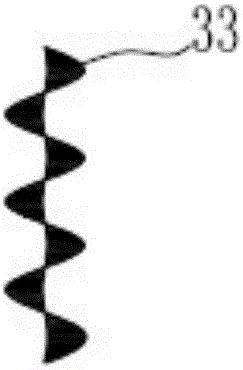
[0040] The cylinder body 10 is provided with a heating gas inlet 11 communicating with the main evaporation mixing chamber 30, and the bottom of the cylinder body 10 is provided with a cooling liquid outlet 18 after heat exchange and a cooling gas outlet 19. The main evaporation mixing chamber 30 is provided with a number of outer finned heat exchange tubes 31, the fins on the outer finned heat exchange tubes 31 are arranged obliquely, which is beneficial to the gas-liquid separation when the heating gas is liquefied while enhancing heat transfer; A refilming device 32 is arranged inside the fin heat exchange tube 31, and its large airflow hole will facilitate the passage of airflow, and can collect the non-atomized liquid bef...

Embodiment 2

[0051] refer to Figure 9 , the structural principle of this embodiment is basically the same as that of Embodiment 1, and the similarities will not be repeated. The only difference is:

[0052] In this embodiment, the outer finned heat exchange tube does not adopt a U-shaped structure, but includes a feed pipe and a discharge pipe arranged in parallel, and floating head pipes are installed at the bottom ends of the feed pipe and the discharge pipe Plate 71, the lower part of the floating head tube plate 71 is provided with a floating head 72, the floating head 72 and the floating head tube plate 71 jointly form an auxiliary evaporation mixing chamber 70, the feed pipe and the discharge pipe It communicates through the auxiliary evaporation mixing chamber 70, and a steam heat exchanger 73 is installed in the auxiliary evaporation mixing chamber 70. The heat exchange tubes of the steam heat exchanger 73 are preferably arranged in a serpentine winding manner, and the lower part ...


PUM


Abstract

The invention belongs to the field of gas and liquid mixing technologies, and particularly relates to a falling-film evaporation efficient gas and liquid mixer. The falling-film evaporation efficient gas and liquid mixer has the advantages that falling-film evaporation principles are adopted, films are formed on the inner wall of an outer fin heat exchange tube by to-be-mixed liquid, to-be-mixed gas flows in the tube to promote film forming effects, pressures rarely drop after the gas is circulated in the heat exchange tube and the liquid is gasified, heating media are arranged on shell pass, the liquid is evaporated to obtain gas to be mixed with the gas, the falling-film evaporation efficient gas and liquid mixer is high in heat exchange efficiency and liquid gasification efficiency, and the gas and the liquid can be uniformly mixed with each other; the falling-film evaporation efficient gas and liquid mixer is particularly applicable to atomization and gasification heating places such as reaction, heating, remixing and diffusion places with requirements on high gas and liquid mixing and gasification and heat exchange efficiency and requirements on low gas pressure drop.

Description

technical field [0001] The invention belongs to the technical field of gas-liquid mixing equipment, and in particular relates to a high-efficiency gas-liquid mixer for falling film evaporation. Background technique [0002] In the occasions of reaction, heating, remixing, diffusion, etc., it is possible to meet the demand of liquid heating, vaporization and mixing with gas. [0003] Existing gas-liquid mixing equipment generally has problems such as low liquid heat exchange and gasification efficiency, poor mixing uniformity, and large pressure drop through gas. Moreover, the mixing process is long and the equipment structure is relatively complicated, which is not conducive to saving investment and reducing maintenance costs. Contents of the invention [0004] In order to solve the above technical problems, the object of the present invention is to provide a falling film evaporation high-efficiency gas-liquid mixer with high efficiency of liquid heat exchange and gasifica...

Claims


Application Information

Patent Timeline
IPC IPC(8): B01D1/22B01D1/30B01F3/02B01F23/10
CPCB01D1/007B01D1/0082B01D1/065B01D1/30B01F23/12
Inventor 黄鹏黄赛黄莉张宇
Owner JIANGSU DUBLE ENG
Why Eureka
Try Eureka