Drilling tools and technology for drilling the main bearing beams of aircraft wings

A profile and tool technology, applied in the field of hole-leading tools, can solve the problems of low efficiency, damage to the original fastener holes of the web, and low precision of hole-leading, and achieve the effects of convenient use, improved work efficiency, and simplified work difficulties

Active Publication Date: 2019-10-25
GUANGZHOU AIRCRAFT MAINTENANCE ENG
View PDF7 Cites 0 Cited by
  • Summary
  • Abstract
  • Description
  • Claims
  • Application Information

AI Technical Summary

Problems solved by technology

Due to the limitation of the narrow space inside the fuel tank, the hole introduction method has low precision and low efficiency, and is prone to damage the original fastener holes of the web

Method used


Image

  • Drilling tools and technology for drilling the main bearing beams of aircraft wings
  • Drilling tools and technology for drilling the main bearing beams of aircraft wings
  • Drilling tools and technology for drilling the main bearing beams of aircraft wings

Examples


specific Embodiment 1

[0044] This embodiment is an embodiment in which the tool of the present invention is used to introduce holes to the repair profile 1 with 8D and 10D original fastener holes on the left wing rear beam of the 737-300 model.

[0045] It uses the tool of the present invention to comprise: 8D-5D, 10D-6D primary guide sleeve each one, 5D-8D, 6D-10D first reaming bit each one, 8D, 10D reamer each one, 5D, One 6D standard drill bit each.

[0046] The following is an explanation of the hole introduction steps of the original fastener hole of 10D:

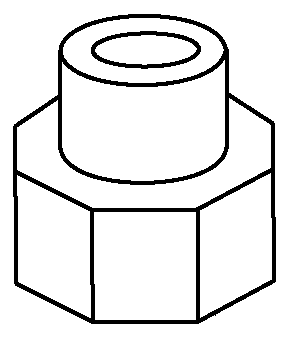
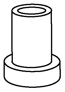
[0047] 1) Introduce a 10D-6D primary guide sleeve 3 into the original fastener hole on the inner web of the fuel tank 2;

[0048] 2) if Figure 4 As shown, a 6D standard drill bit 5 is used to drill initial fastener holes on the repair profile 1 from the inside of the oil tank 2 to the outside through the primary guide sleeve 3 .

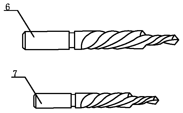
[0049] 3) if Figure 5As shown, use the first reaming drill of 6D-10D on the outside of the fuel tank 2 to...

specific Embodiment 2

[0053] This embodiment is an embodiment in which the tool of the present invention is used to introduce holes to the repair profile 1 with 12D and 14D original fastener holes on the left wing rear beam of the 737-300 model.

[0054] Tools which use the invention include:

[0055] One primary guide bush for 12D-8D, 14D-10D, one secondary guide bush for 8D-5D, 10D-6D, one first reaming bit for 12D-8D, 14D-10D, one for 5D-8D, One second reaming drill for 6D-10D, one reamer for 12D and 14D, one standard drill for 5D and 6D.

[0056] The following is an explanation of the hole guide steps of the 12D original fastener hole:

[0057] 1) Insert the 12D-8D primary guide sleeve 3 into the original fastener hole on the inner web of the fuel tank 2, and then insert the 8D-5D secondary guide sleeve 4 into the inner diameter of the guide shaft of the above-mentioned primary guide sleeve 3 .

[0058] 2) if Figure 6 As shown, a 5D standard drill bit 5 is used to drill initial fastener ho...


PUM


Abstract

The invention discloses a hole guiding tool and technology for drilling a repair sectional bar of an airplane greater-wing main bearing beam. One-stage guide sleeves, two-stage guide sleeves, standard drill bits, reamers and two-stage broaching bits are used for drilling, wherein the outer diameter of an one-stage guide shaft is matched with the required hole diameter of the sectional bar, and the inner diameter of one-stage guide shaft is matched with the outer diameter of each two-stage guide sleeve; and according to each two-stage broaching bit, a guiding drill bit extends outwards from each drill bit body. Compared with step-by-step broaching after directly drilling the hole by a drill bit in the prior art, the hole guiding tool disclosed by the invention has the advantage the hole guiding operation is performed by the guide sleeves, so that the phenomenon that the structure of a web is damaged due to the damage of the original fastener hole diameter of the web is avoided; and besides, a conventional one-stage broaching bit is improved into the two-stage broaching bit, so that centering procedures during broaching twice can be completed once. The hole guiding tool disclosed by the invention has the characteristics of being simple to operate, high in hole guiding precision, simplified in procedures, and the like.

Description

technical field [0001] The invention relates to a hole-leading tool, in particular to a hole-leading tool used for drilling a section bar for repairing a 737CL large-wing main bearing beam. The invention also relates to a hole-leading process for the tool to be used for drilling profile holes for repairing main bearing beams of aircraft wings. Background technique [0002] Boeing 737CL is the main model of the civil aviation transportation industry, and the aging problem is getting worse day by day. After more and more flight hours of this model, the specific fasteners of the main load-bearing structure (upper edge strip) of the rear beam of the large wing Penetrating cracks generally appear at the position of the hole, seriously affecting the safety of the aircraft. [0003] The upper edge of the rear beam of the wing is 4.3 meters long, and it is an L-shaped configuration, extending along the span direction. The upper flange is embedded in the fuel tank of the wing and co...

Claims


Application Information

Patent Timeline
Patent Type & Authority Patents(China)
IPC IPC(8): B23B47/28
CPCB23B47/287
Inventor 欧阳忠华孔志颜金汤健王涛严广亮吴鸿程李汉鹏武春曾祥浩
Owner GUANGZHOU AIRCRAFT MAINTENANCE ENG
Why Eureka
Try Eureka