
Workpiece polishing device

A workpiece and grinding roller technology, applied in the field of workpiece processing, can solve problems such as operator injury, danger, and troublesome operation, and achieve the effect of improving efficiency and preventing splashing and hurting people.

Active Publication Date: 2017-06-13
CHONGQING TENGTONG IND DESIGN
View PDF8 Cites 14 Cited by
  • Summary
  • Abstract
  • Description
  • Claims
  • Application Information

AI Technical Summary

Problems solved by technology

[0004] This workpiece grinding device solves the problem that the hand will be sore during the manual grinding process of holding the workpiece, which will cause the grinder to fall off from the hand and cause injury to the operator. However, this device also has the following disadvantages: 1. The clamping seat is square After the workpiece is clamped, the grinding machine can only grind one surface of the square workpiece. If other surfaces need to be polished, the square workpiece needs to be removed and replaced with another surface before grinding, which makes the operation troublesome and the grinding efficiency is low; 2 , During the grinding process, the square workpiece will produce iron filings, and the iron filings splash everywhere, which is easy to hurt people and is more dangerous

Method used


Image

  • Workpiece polishing device
  • Workpiece polishing device

Examples


Embodiment Construction

[0016] The present invention will be described in further detail below by means of specific embodiments:

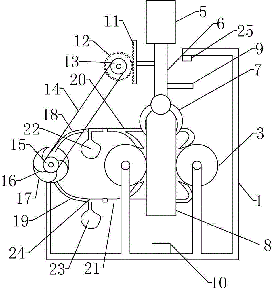
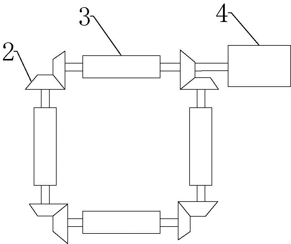
[0017] The reference signs in the drawings of the description include: frame 1, bevel gear 2, grinding roller 3, motor 4, reciprocating cylinder 5, telescopic rod 6, jaw 7, square workpiece 8, connecting rod 9, first limit switch 10. Rack 11, gear 12, first roller 13, belt 14, second roller 15, impeller 16, sealing shell 17, first three-way pipe 18, second three-way pipe 19, first branch pipe 20, The second branch pipe 21 , the first collection bag 22 , the second collection bag 23 , the blocking piece 24 , and the second limit switch 25 .

[0018] Example basic reference figure 1 with figure 2Shown: The workpiece grinding device includes a frame 1, on which there are 4 grinding rollers 3 that are connected end-to-end through bevel gear 122. The grinding rollers 3 are driven by a motor 4, and a reciprocating cylinder is installed above the grinding rollers 3. 5. The l...


PUM


Abstract

The invention discloses a workpiece polishing device comprising a machine frame. The machine frame is connected with polishing rollers, a reciprocating air cylinder, a first limiting switch and a second limiting switch. The reciprocating air cylinder is provided with a telescopic rod. A clamping jaw is arranged on the telescopic rod. The telescopic rod is provided with a connecting rod and connected with a rack. The rack is meshed with a gear. The gear is coaxially connected with a first rolling wheel. The first rolling wheel is provided with a second rolling wheel through belt tensioning. The second rolling wheel is coaxially connected with an impeller. The impeller is provided with a seal shell. The seal shell communicates with a first t-branch pipe and a second t-branch pipe. The first t-branch pipe communicates with a first collecting bag and a first forked pipe. Pipe openings of the first forked pipe are located at feeding openings of the polishing rollers. The second t-branch pipe communicates with a second collecting bag and a second forked pipe. Pipe openings of the second forked pipe are located at discharging openings of the polishing rollers. Stop sheets are arranged in both the first t-branch pipe and the second t-branch pipe. Compared with the prior art, the workpiece polishing device improves the work efficiency of polishing and collects generated iron chips.

Description

technical field [0001] The invention relates to the field of workpiece processing, in particular to a workpiece grinding device. Background technique [0002] After the square workpiece is processed, the particles and impurities on the surface need to be removed to obtain a flat surface. When processing the surface of the square workpiece, the square workpiece is first clamped, and then the hand-held grinder moves back and forth along the square workpiece to polish the surface of the square workpiece. , due to the need to hold the grinding machine for a long time, the hand will be sore, causing the grinding machine to fall off from the hand, causing injury to the operator. [0003] In order to solve the above problems, the patent document CN201410571435.1 is a workpiece grinding device, which includes a base, a first support seat and a second support seat arranged on the base, and a clamping seat is fixed on the first support seat. The base plate is fixed on the second supp...

Claims


Application Information

Patent Timeline
Patent Type & Authority Applications(China)
IPC IPC(8): B24B19/00B24B41/00B24B55/06
CPCB24B19/00B24B41/00B24B55/06
Inventor 李庸健
Owner CHONGQING TENGTONG IND DESIGN
Learn More