Paperboard processing device

A technology for processing equipment and cardboard, applied in the direction of metal processing, cardboard items, etc., can solve the problems of non-compliance with the grain direction, reduce the flatness of cutting, and not easy to cut, so as to achieve smooth cuts, avoid equipment jamming, and improve The effect of flatness

Active Publication Date: 2017-06-13
山东省新征程工业科技有限公司
View PDF7 Cites 2 Cited by
  • Summary
  • Abstract
  • Description
  • Claims
  • Application Information

AI Technical Summary

Problems solved by technology

[0004] However, there is a problem in the above patent. The honeycomb paper core that needs to be cut slides down from the paper guide plate by its own weight to discharge the material. The cardboard is easy to bend, and the equipment is easy to be stuck if the material is not discharged in time, which greatly limits Improve the production efficiency of honeycomb paper core
In addition, because the honeycomb paper core is discharged by its own weight, it cannot be effectively fixed during the cutting process, and it is easy to shift during the cutting process, which reduces the flatness of the cutting
[0005] There is still a problem. When these devices are cutting honeycomb cardboard, the cutting direction of the cutter does not conform to the grain direction of the paper core. As a result, it is not easy to cut when cutting. Forcibly cutting the cardboard will cause the cardboard to be cut. It is messy and even pitted, which is not convenient for the combination or processing of the cut cardboard, and it needs people to re-decorate the cut

Method used


Image

  • Paperboard processing device
  • Paperboard processing device

Examples


Embodiment 1

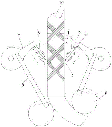
[0022] Embodiment 1 is basically as attached figure 1 Shown: a cardboard processing equipment, including a material introduction chamber 1 for guiding the cardboard to the cutting position; a through hole is symmetrically opened in the middle of the material introduction chamber 1, and a cutting chamber 2 is fixedly installed on the through hole, and the inclination angle of the cutting chamber 2 is the same as The honeycomb pattern of the paper core is the same; the cutting cavity 2 is slidingly connected with 6, and the top of the blade 6 is provided with a limit block 3, and the limit block 3 is connected with the upper edge of the cutting cavity 2 by a spring 5. The part of the stop block 3 that is knocked by the cam 7 is provided with a concave cavity, and the surface of the concave cavity is provided with a layer of rubber film 4; Both sides of the outlet of the material introduction cavity 1 are provided with round rollers 9 that can drive the discharge. The rotating sp...

Embodiment 2

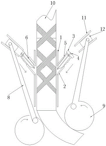
[0026] The difference between this embodiment and Embodiment 1 is that the beating part is a guide rail 11 installed above the limit block, and a slider 12 slidably connected to the guide rail 11 and eccentrically hinged with the round roller; the length of the guide rail is greater than that of the slider Upper limit position when driven. The round roller and the slider constitute a slider crank mechanism, which changes the periodic rotation of the round roller into the reciprocating motion of the slider 12, thereby realizing the beating of the limit block 3 .


PUM


Abstract

The invention belongs to the field of paperboard processing devices, and particularly relates to a paperboard processing device. The paperboard processing device comprises a guiding cavity used for guiding a paperboard to a cutting position; through holes are symmetrically formed in the middle of the guiding cavity; cutting cavities are fixed on the through holes; the inclination angles of the cutting cavities are the same as a honeycomb line of a paper core; blades are arranged in the cutting cavities in a sliding mode; limiting blocks are arranged at the tops of the blades and are connected to the upper edges of the cutting cavities through springs; the two sides of the outlet of the guiding cavity are provided with round rollers capable of driving the paperboard to be discharged; and cams are hinged to the round rollers through connecting rods and can rotate to beat the limiting blocks. According to the paperboard processing device, the paperboard is driven to be discharged mechanically through the special structure so that the cutting efficiency can be improved; and in addition, notches are smooth, the subsequent combination of paperboards is facilitated, and artificial modifying and cutting are not needed.

Description

technical field [0001] The utility invention belongs to the field of cardboard processing equipment, and in particular relates to a cardboard processing equipment. Background technique [0002] As we all know, cutting the honeycomb paper core is an essential process in the production process of the honeycomb paper core, and the quality of the cutting device design directly affects the production efficiency and production quality of the honeycomb paper core. [0003] At present, Chinese patent authorization announcement number CN100586671C discloses a shearing mechanism for a honeycomb paper core automatic production line, including a frame and a shearing device. There is an arc-shaped paper guide plate above the table, and a lifting mechanism that can adjust the height of the table is provided below the above machine table. The shearing device includes a fixed cutter, a movable cutter, and a driving mechanism, wherein: the fixed cutter and the movable cutter are vertically ...

Claims


Application Information

Patent Timeline
Patent Type & Authority Applications(China)
IPC IPC(8): B26D1/06B26D7/01B26D7/32B26D7/18B26D5/16B31D3/02
CPCB26D1/065B26D5/16B26D7/01B26D7/1854B26D7/32B26D2007/322B31D3/02
Inventor 余喜玲
Owner 山东省新征程工业科技有限公司
Why Eureka
Try Eureka