
Rainwater collecting device for municipal gardens

A rainwater collection device and rainwater collection technology are applied in water supply devices, grease/oily substance/floating matter removal devices, sewage discharge, etc., which can solve problems such as increased workload of staff, harm to human body, increased work costs, etc., and achieve energy efficiency. The loss is small, the effect of reducing pollution and reducing work costs

Active Publication Date: 2017-06-13
温州市龙湾建设园林绿化工程有限公司
View PDF8 Cites 19 Cited by
  • Summary
  • Abstract
  • Description
  • Claims
  • Application Information

AI Technical Summary

Problems solved by technology

[0005] Although this utility model facilitates the irrigation of trees and effectively saves water resources, with the development of modern society, a large amount of polluting gases such as vehicle exhaust and factory exhaust gas have accumulated in the air, and they will be incorporated into rainwater in large quantities at the beginning of rainfall. , so that a large amount of pollutants contained in the early rainwater are harmful to the human body. If the initial rainwater is not treated in any way, it will be directly recycled with the relatively clean rainwater in the later period. When the staff processes all the collected rainwater , which not only increases the workload of the staff, but also increases the cost of work

Method used


Image

  • Rainwater collecting device for municipal gardens
  • Rainwater collecting device for municipal gardens
  • Rainwater collecting device for municipal gardens

Examples


Embodiment Construction

[0033] The present invention will be described in further detail below in conjunction with the accompanying drawings.

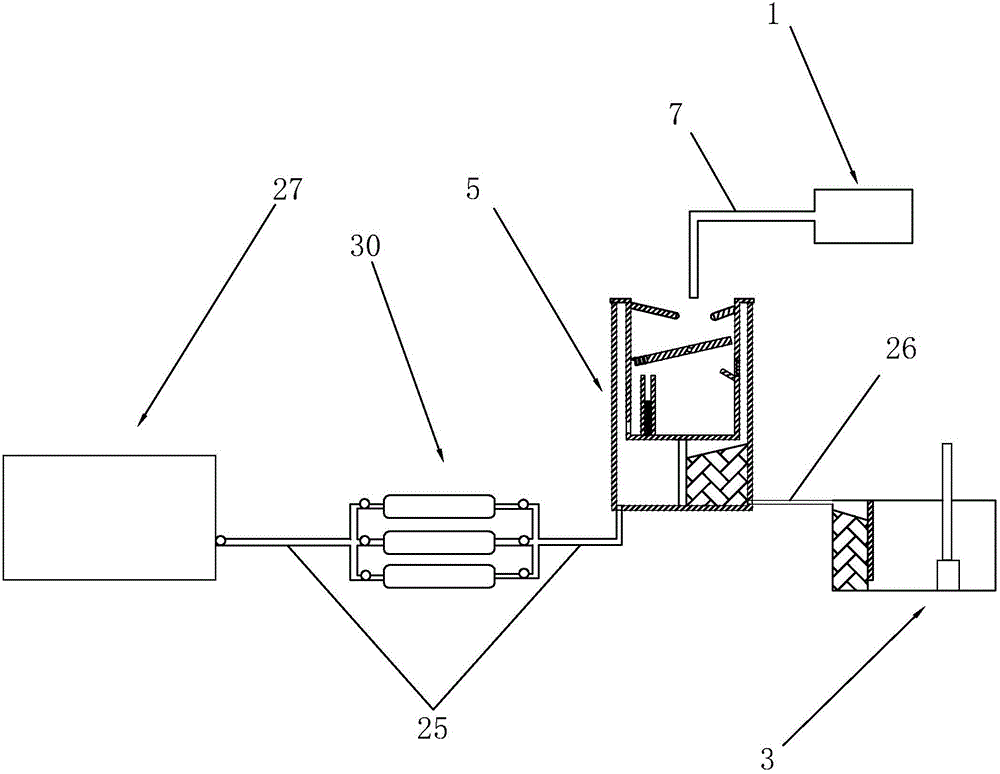
[0034] like figure 1 As shown, the rainwater collection mechanism 1 puts rainwater in the initial rainwater abandonment mechanism 5 through the first pipeline 7, and the rainwater is separated by the initial rainwater abandonment mechanism 5, and the rainwater in the early stage with serious pollution passes through the waste flow control mechanism 30. The second pipeline 25 communicates with the waste water tank 27 , and the relatively clean late rainwater communicates with the water storage tank 3 through the third pipeline 26 .

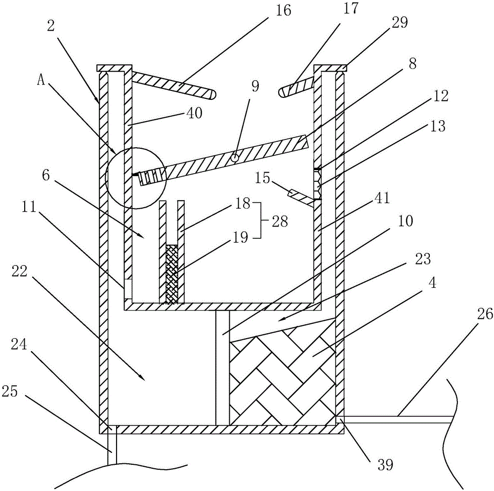
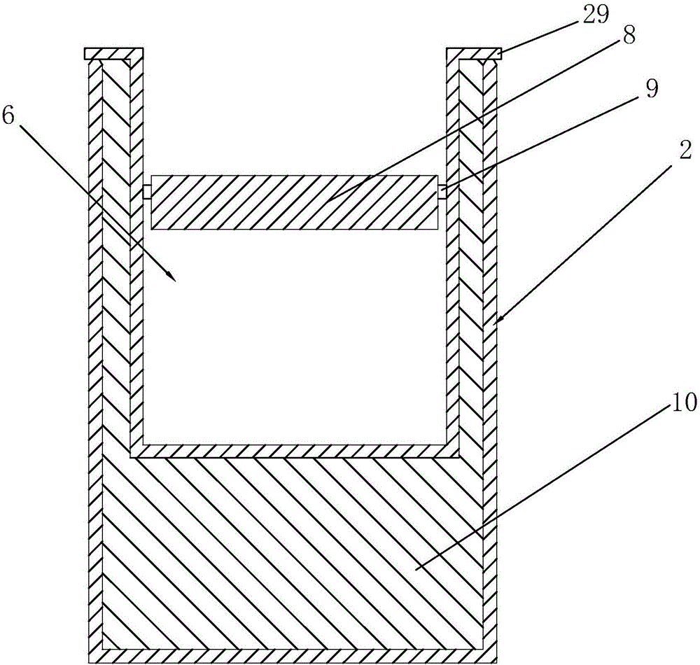
[0035] combine figure 2 and image 3 As shown, the rainwater collection box 2 is welded with a partition plate 10, the partition plate 10 is in the shape of a "U" and divides the rainwater collection box 2 into two parts, which are respectively the discarding part 22 and the recovery part 23, and the recovery part 23 The first f...


PUM


Abstract

The invention discloses a rainwater collecting device for municipal gardens. According to the technical scheme, the rainwater collecting device mainly comprises a rainwater collecting mechanism, a rainwater collecting tank and a water storage tank and is characterized in that a first filter mechanism is arranged in the rainwater collecting tank, the rainwater collecting mechanism is provided with a first pipeline used for conveying rainwater collected by the rainwater collecting mechanism into the rainwater collecting tank, and a preliminary rainwater flow abandoning mechanism used for separating the rainwater collected by the rainwater collecting tank is further arranged in the rainwater collecting tank; the preliminary rainwater flow abandoning mechanism comprises a rainwater flow abandoning tank located in the rainwater collecting tank; a rainwater flow separating plate is arranged in the rainwater flow abandoning tank, and a central shaft allowing the rainwater flow separating plate to rotate is arranged in the rainwater flow abandoning tank; a rainwater flow abandoning wall and an overflow wall are arranged in the rainwater flow abandoning tank and are parallel with the axis of the central shaft, the rainwater flow abandoning wall is provided with a rainwater flow abandoning hole, the overflow wall is provided with an overflow hole, one end, close to the rainwater flow abandoning wall, of the rainwater flow separating plate is provided with a water filtering hole, the distance from the central shaft to the overflow wall is smaller than the distance from the central shaft to the rainwater flow abandoning wall, a gap is reserved between the rainwater flow abandoning wall and the rainwater flow separating plate, and a gap is reserved between the overflow wall and the rainwater flow separating plate.

Description

technical field [0001] The invention relates to the field of municipal gardens, in particular to a rainwater collection device for municipal gardens. Background technique [0002] Due to the rapid development of urbanization and the expansion of impermeable areas such as roads, gardens, landscapes, urban residential areas, and large building complexes, rainwater can no longer infiltrate into the ground to replenish groundwater. The surrounding water environment and ecological environment are deteriorating; on the other hand, when it rains heavily, the rainwater quickly gathers to cause ground water and local floods; urban water shortages, water environment deterioration, ecological environment damage, and urban storm floods are increasingly prominent. [0003] If in urban construction, through the extensive development of rainwater collection and utilization, the drainage of the city can be reduced, and the threat of urban flood disasters can be reduced. At the same time, th...

Claims


Application Information

Patent Timeline
IPC IPC(8): E03F1/00E03F5/10E03F5/14
CPCE03F1/00E03F5/10E03F5/14E03F2201/10
Inventor 陈智林陈玲雪夏浩霄陈姬季艳艳方芳
Owner 温州市龙湾建设园林绿化工程有限公司
Learn More