
Cooling water pump for internal combustion engine and production process of cooling water pump

A technology for cooling water pumps and internal combustion engines, which is applied in the cooling of engines, liquid fuel engines, components of pumping devices for elastic fluids, etc. , reduce the impact, improve the effect of pump flow

Inactive Publication Date: 2017-06-13
YANCHENG DUOWEI GROUP
View PDF0 Cites 7 Cited by
  • Summary
  • Abstract
  • Description
  • Claims
  • Application Information

AI Technical Summary

Problems solved by technology

[0003] Most of the existing cooling water pumps for internal combustion engines are mechanical water pumps. The operation of the water pump depends on the transmission of the engine shaft. When the engine speed is high, the water pump speed is high and the flow rate is increased. When the engine speed is low, the flow rate is reduced; The engine itself does not need the cooling system to work, but the engine water pump will start to work with the engine running, which will cause the engine to warm up for a long time, the engine fuel consumption is high, and the emission is poor. The flow rate of the water pump cannot meet the needs of the engine cooling system. make adjustments

Method used


Image

  • Cooling water pump for internal combustion engine and production process of cooling water pump
  • Cooling water pump for internal combustion engine and production process of cooling water pump
  • Cooling water pump for internal combustion engine and production process of cooling water pump

Examples


Embodiment 1

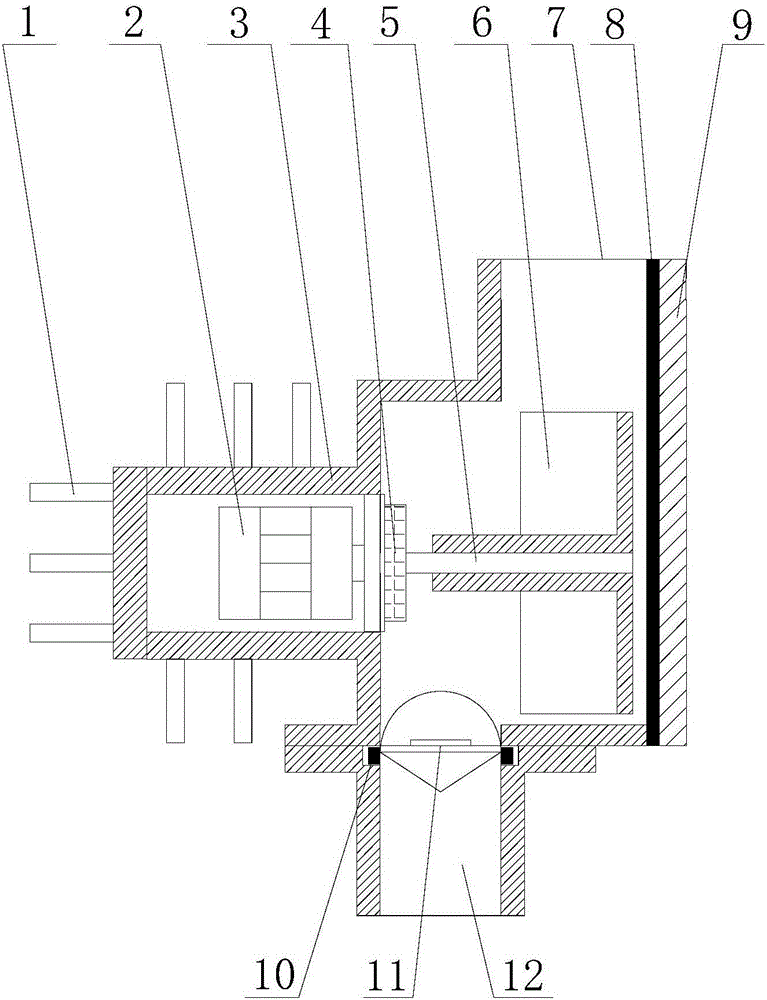
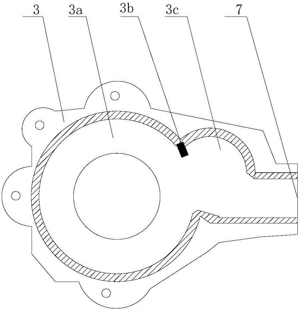
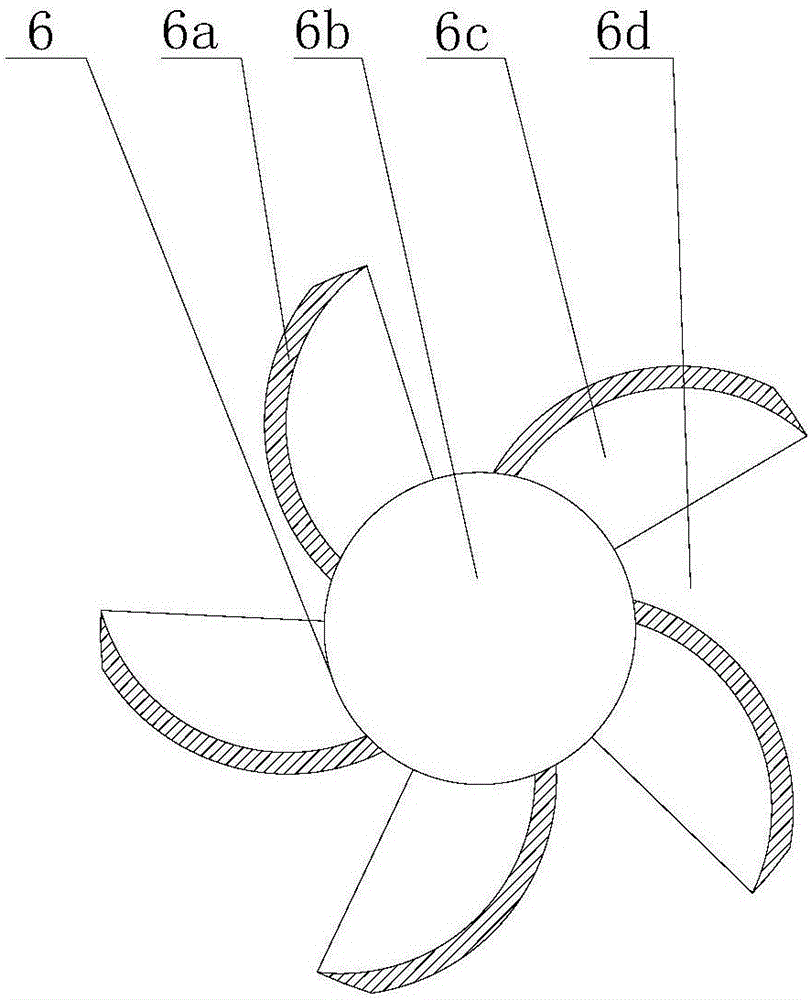
[0070] This embodiment provides a cooling water pump for an internal combustion engine, such as figure 1 , 2 As shown in and 3, it includes a water pump housing 3, a rotating shaft 5, a cover plate 9 and an impeller 6. The water pump housing 3 is formed with a cavity 3a, the rotating shaft 5 is installed in the middle of the cavity 3a through a bearing, and the impeller 6 can rotate along its own axis. Installed on the rotating shaft 5, the cover plate 9 is affixed to the side of the water pump housing 3 that is formed with the cavity 3a; the water pump housing 3 is provided with a water inlet 12 and a water outlet 7, and the water inlet 12 of the water pump housing 3 is provided with In the temperature control valve 11, a partition tongue 3b is formed near the water outlet 7 in the cavity 3a, and a vortex chamber flow channel 3c is formed between the partition tongue 3b and the water outlet 7, and the vortex chamber flow channel 3c is arc-shaped;

[0071] The impeller 6 incl...

Embodiment 2

[0103] This embodiment provides a kind of cooling water pump for internal combustion engine, comprising water pump housing 3, rotating shaft 5, cover plate 9 and impeller 6, water pump housing 3 is shaped on cavity 3a, rotating shaft 5 is installed in the middle part of cavity 3a through bearing, impeller 6 is installed on the rotating shaft 5 that can rotate along its own axis, and the cover plate 9 is fixedly connected with the side of the cavity 3a of the water pump housing 3; the water pump housing 3 is provided with a water inlet 12 and a water outlet 7, and the water pump housing 3 The water inlet 12 is provided with a temperature control valve 11, and a partition tongue 3b is formed near the water outlet 7 in the cavity 3a, and a vortex chamber flow channel 3c is formed between the partition tongue 3b and the water outlet 7, and the vortex chamber flow channel 3c is Arc type;

[0104] The impeller 6 includes a hub 6b, a disc 6c and a blade 6a, the hub 6b is fixed to the...


PUM

PropertyMeasurementUnit
thicknessaaaaaaaaaa

Abstract

The invention discloses a cooling water pump for an internal combustion engine. The cooling water pump comprises a water pump shell, a rotary shaft, a cover plate and an impeller. A cavity is formed in the water pump shell, the rotary shaft is mounted in the middle of the cavity through a bearing, and the impeller can be mounted on the rotary shaft in the manner of rotating around the axis of itself. The cover plate is fixedly connected with the side, provided with the cavity, of the water pump shell. The water pump shell is provided with a water inlet and a water outlet, a separation tongue is machined in the position, close to the water outlet, in the cavity, a volute chamber passageway is machined between the separation tongue and the water outlet, and the volute chamber passageway is in an arc shape. The impeller comprises a hub, a wheel disc and blades. The hub is fixedly connected with the center of the wheel disc, the blades are in arc sheet shapes, and the at least two blades are evenly arranged on the wheel disc around the hub in a spaced manner. At least two openings are formed in the wheel disc, and the openings are formed between the blades. According to the cooling water pump for the internal combustion engine, the openings are formed in the wheel disc, the size and mass of the impeller are reduced, the available volume in the cavity is increased, and under the condition of not changing the boundary dimension of the water pump and a connector, the flow of the water pump is increased, and energy consumption is reduced.

Description

technical field [0001] The invention relates to a cooling water pump for an internal combustion engine and a production process thereof, belonging to the technical field of auto parts. Background technique [0002] When the internal combustion engine is working, it needs to be cooled to prevent the temperature from rising. Usually, the cooling water pump is used to press the cooling water for water cooling. Due to the complex structure of the internal combustion engine, the internal cooling channel is curved and narrow, and the resistance to water flow is large. The size of the flow rate has become the key to the cooling effect of the internal combustion engine. [0003] Most of the existing cooling water pumps for internal combustion engines are mechanical water pumps. The operation of the water pump depends on the transmission of the engine shaft. When the engine speed is high, the water pump speed is high and the flow rate is increased. When the engine speed is low, the f...

Claims


Application Information

Patent Timeline
Patent Type & Authority Applications(China)
IPC IPC(8): F01P5/10F04D29/42F04D29/24C22C38/06C22C38/04C22C38/42C22C38/46C22C38/44C22C38/50C22C38/54C22C38/60C22C33/04B22C9/04C21D1/18C22C38/32C22C38/28C22C38/24C22C38/30C22C38/26C22C38/22
CPCF01P5/10B22C9/04C21D1/18C22C33/04C22C38/002C22C38/005C22C38/007C22C38/008C22C38/04C22C38/06C22C38/22C22C38/24C22C38/26C22C38/28C22C38/30C22C38/32C22C38/42C22C38/44C22C38/46C22C38/50C22C38/54C22C38/60F04D29/242F04D29/426
Inventor 高军陈杰殷志华
Owner YANCHENG DUOWEI GROUP
Learn More