
High-rigidity transmission mechanism

A transmission mechanism, high rigidity technology, applied in transmission devices, mechanical equipment, belts/chains/gears, etc., to achieve the effect of high transmission rigidity, improved rigidity, and reliable transmission

Active Publication Date: 2017-06-13
SHANGHAI XINYUE METER FACTORY
View PDF6 Cites 4 Cited by
  • Summary
  • Abstract
  • Description
  • Claims
  • Application Information

AI Technical Summary

Problems solved by technology

[0005] The technical problem to be solved by the present invention is to provide a high-rigidity transmission mechanism, which can solve the problems of increasing the stiffness of the transmission mechanism and effectively controlling the clearance of the transmission mechanism under the large load and complex environment of the missile flight

Method used


Image

  • High-rigidity transmission mechanism
  • High-rigidity transmission mechanism
  • High-rigidity transmission mechanism

Examples


Embodiment Construction

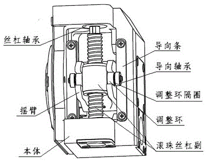
[0017] Such as figure 1 Shown is a high-rigidity transmission mechanism, which is composed of a body, a screw bearing, a ball screw pair (including a ball screw and a ball nut), a rocker arm, an adjusting ring, an adjusting ring spacer, a guide bearing, and a guide bar.

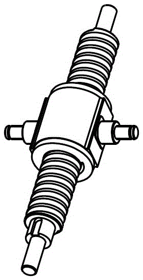
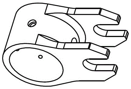
[0018] Figure 2-5 It is a schematic diagram of the structure of the ball screw pair, the rocker arm, the adjustment ring and the guide bar.

[0019] Such as figure 1 As shown, the ball screw makes a circular motion. Due to the existence of the guide bearing during the motion, the ball nut can only move up and down. The translation is transformed into the circular motion of the rocker arm. The ball screw is fixed on the body through the screw bearings at both ends. In order to improve the bearing capacity, the screw bearing adopts double-row deep groove ball bearings; a support arm protrudes from each end of the ball nut, and the cylindrical section of the support arm is connected with the adjustment ring...


PUM


Abstract

The invention discloses a high-rigidity transmission mechanism. The high-rigidity transmission mechanism comprises a mechanism body, screw bearings, a ball screw pair, rocker arms, adjusting rings, adjusting ring spacing collars, guide bearings, and guide strips. The ball screw pair does circular motion, in the moving process, a ball nut can only do vertical translation due to existing of the guide bearings, supporting arms extending from the two ends of the ball nut are connected with rocker arm shifting forks through the adjusting rings, and accordingly, the vertical translation of the nut is converted into circular motion of the rocker arms. Force produced through load torque can be uniformly distributed through the two supporting arm structures of the ball nut, deformation of the rocker arms is decreased, and the rigidity is improved; the outer ends of the supporting arms of the ball nut are provided with the guide bearings to make contact with the guide strips, self rotating of the ball nut is limited, and the gap in the ball screw pair is eliminated; meanwhile, the inner circle and the outer circle of each adjusting ring are in interference fit so that the clearance can be eliminated; and the adjusting rings and the rocker arms are made of a stainless steel material and subjected to heat treatment so that the hardness and abrasion resistance of the surfaces of the adjusting rings and the surfaces of the rocker arms can be improved.

Description

technical field [0001] The invention relates to the field of mechanical transmission, in particular to a high-rigidity transmission mechanism based on a ball screw pair in a servo system such as an electric steering gear. Background technique [0002] The transmission mechanism is an important part of the electric steering gear, which is widely used in the fields of missiles, launch vehicles, torpedoes and other weapon systems. [0003] The electric steering gear requires the transmission mechanism to have a large reduction ratio and a small volume and weight. In order to make up for the shortcomings of small reduction ratio of gear transmission and low efficiency of worm gear transmission, electric steering gear mostly adopts the transmission form of ball screw pair. [0004] During the flight of the aircraft, the steering gear needs to overcome the aerodynamic load on the rudder surface. At the same time, the harsh flight vibration environment can easily stimulate the sel...

Claims


Application Information

Patent Timeline
Patent Type & Authority Applications(China)
IPC IPC(8): F16H25/22F16H25/24
CPCF16H25/2209F16H25/24F16H2025/2436
Inventor 潘强陶键武晓峰
Owner SHANGHAI XINYUE METER FACTORY
Learn More