Baffle rod type preheater for high-pressure boiler water and chemical reaction device

A high-pressure boiler and preheater technology, which is applied in the direction of heat exchanger shell, indirect heat exchanger, heat exchanger type, etc. Low thermal efficiency and other problems, to achieve the effect of reducing material requirements and manufacturing difficulty, eliminating hidden dangers of high temperature stress, and prolonging service life

Pending Publication Date: 2017-06-13
NANJING JUTUO CHEM TECH
View PDF9 Cites 2 Cited by
  • Summary
  • Abstract
  • Description
  • Claims
  • Application Information

AI Technical Summary

Problems solved by technology

[0005] In view of the problems of the existing waste heat recovery device, such as large amount of materials, low heat exchange efficiency, unfavorable maintenance, difficult manufacturing, concentrated heat stress on the tube sheet, and easy crackin

Method used


Image

  • Baffle rod type preheater for high-pressure boiler water and chemical reaction device
  • Baffle rod type preheater for high-pressure boiler water and chemical reaction device

Examples


Embodiment 1

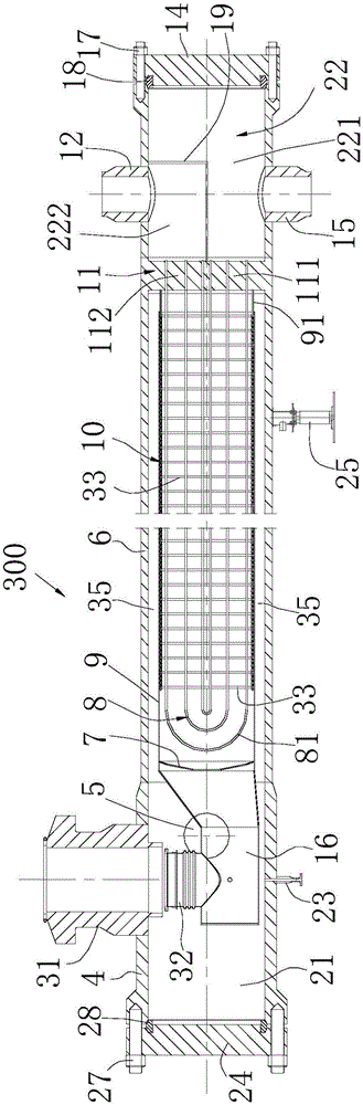
[0024] refer to figure 1 , a high-pressure boiler water baffle rod preheater 300, which includes a shell 6 closed at both ends, the shell 6 is cylindrical, a front end cover 24 is installed at one end of the shell 6, and a rear end cover is installed at the other end 14. Front-end cover bolts 27 fasten the front-end cover 24 to one end of the casing, and a front-end seal 28 is installed between the front-end cover 24 and the end surface of the casing. The rear end cover bolts 17 fasten the rear end cover 14 on the other end of the casing, and a rear end seal 18 is installed between the rear end cover 14 and the end surface of the casing.

[0025] A tube plate 11 is arranged in the shell 6, and the tube plate 11 divides the inner cavity of the shell 6 into a heat exchange cavity and a water cavity 22; Divided into a water inlet chamber 221 and a water outlet chamber 222 that are not connected to each other, the partition plate 19 divides the tube plate 11 into two parts: the w...

Embodiment 2

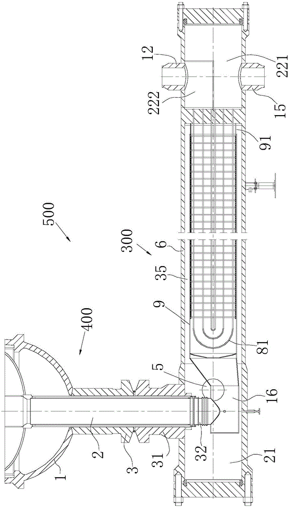
[0034] see figure 2 , a chemical reaction device 500 for an exothermic reaction, which includes the high-pressure boiler water baffle rod preheater 300 described in Embodiment 1 and a reactor 400, and the shell 1 of the reactor 400 is connected by a connecting flange 3 To the inlet sleeve 31 of the preheater 300, the reaction gas outlet pipe 2 of the reactor 400 is connected to the gas inlet 32 ​​of the preheater 300, and a metal soft joint is installed between the reaction gas outlet pipe 2 and the gas inlet 32 .

[0035] The reaction gas that has completed the reaction in the reactor 400 enters the preheater 300 through the reaction gas outlet pipe 2 and the gas inlet 32, and then the reaction gas enters the tube bundle sleeve 9 through the high-temperature inner header 16, and passes through the tube bundle sleeve 9 The internal reactant gas passes through the gaps between the U-shaped heat exchange tubes 81, exchanges heat with the cooling water in the U-shaped heat exch...


PUM


Abstract

The invention discloses a baffle rod type preheater for high-pressure boiler water. The baffle rod type preheater comprises a shell and a tube plate, wherein the tube plate divides an inner cavity of the shell into a heat exchange cavity and a water cavity; the water cavity is divided into a water inlet cavity and a water outlet cavity which are not communicated with each other; a tube bundle sleeve is arranged in the shell; in the tube bundle sleeve, certain ends of U-shaped heat exchange tubes are communicated with the water inlet cavity through the tube plate, while the other ends of the U-shaped heat exchange tubes are communicated with the water outlet cavity through the tube plate; the shell is connected with a high-pressure external connection box; a communicating part is arranged between the tube bundle sleeve and the tube plate; one end, far away from the tube plate, of the tube bundle sleeve is formed into a high-temperature internal connection box; a gas passage is arranged between the outer wall of the tube bundle sleeve and the inner wall of the shell; a gas entering through a gas inlet can pass through the high-temperature internal connection box, gaps among the U-shaped heat exchange tubes, the communicating part and the gas passage in sequence, and then is discharged from the preheater through a gas outlet. The invention also discloses a chemical reaction device for an exothermal reaction, which is provided with the preheater. The baffle rod type preheater has advantages that the heat stress of the tube plate is less, the maintenance is facilitated, the manufacturing difficulty is low, and the like.

Description

technical field [0001] The invention belongs to the technical field of chemical equipment, and is a waste heat recovery device for a chemical reactor, specifically, a horizontal high-pressure boiler water baffle rod type with low material requirements, low manufacturing cost, easy maintenance, and high thermal efficiency. Preheater. Background technique [0002] At present, the waste heat recovery device after the chemical reaction has been greatly improved. Usually, the high temperature and high pressure are separated, and the form of double casing or triple casing is adopted, and the process gas enters from the inner pipe and exits from the outer casing. Although It separates the high-temperature and high-pressure areas, but because of the multiple casings, it is cumbersome to manufacture and wasteful in material consumption; in addition, the heat exchange efficiency is not high due to the multiple casings. [0003] The heat exchange tubes in traditional waste heat recove...

Claims


Application Information

Patent Timeline
IPC IPC(8): F28D7/06F28F9/02F28F9/24B01J19/00
CPCB01J19/002F28D7/06F28F9/028F28F9/24
Inventor 卢健王雪林聂忠峰
Owner NANJING JUTUO CHEM TECH
Why Eureka
Try Eureka