Liquid level measurement method, liquid level measurement device and system
A liquid level measurement device and technology for liquid level measurement, which are used in measurement devices, liquid/fluid solids measurement, lubrication indicating devices, etc., and can solve problems such as oil tank explosion, low accuracy, and electric leakage.
Inactive Publication Date: 2017-06-13
李成
0 Cites 0 Cited by
AI-Extracted Technical Summary
Problems solved by technology
[0005] The purpose of the present invention is to provide a liquid level measurement method to solve the risk of electric leakage of the existing electronic liquid level gauge and...
Method used
Preferably, can be provided with isolating cover etc. in the outside of monitor 2, thereby monitor 2 is better protected by is...
Abstract
The invention discloses a liquid level measurement method, a liquid level measurement device and a system, and relates to the technical field of liquid level measurement, in order to solve the problem that the existing electronic liquid level gauge has the risk of electric leakage and easily leads to the explosion of the oil tank, and the indirect conversion method is long-term The technical problem of low accuracy when calculating the liquid level height after use. The liquid level measurement method of the present invention comprises the following steps: monitoring the heat distribution field on the surface of the tank body; and determining the liquid level height in the tank body according to the heat distribution field. Monitor the heat distribution field on the surface of the tank, form a corresponding thermal image according to the heat distribution field, and determine the liquid level in the tank (the temperature of the liquid part in the tank) according to the different temperatures represented by different colors on the thermal image Different from the temperature without the liquid part, the color reflected on the thermal image is also different); there is no need to set up electronic products in the tank, and it is not necessary to open the tank when measuring the liquid level, avoiding the conversion method but using the The tank is monitored and measured in real time.
Application Domain
Machines/enginesLevel indicators +1
Technology Topic
EngineeringLiquid level measurement
Image
Examples
- Experimental program(1)
Example Embodiment
[0029] The technical solutions of the present invention will be clearly and completely described below in conjunction with the accompanying drawings. Obviously, the described embodiments are part of the embodiments of the present invention, rather than all of them. Based on the embodiments of the present invention, all other embodiments obtained by those of ordinary skill in the art without creative work shall fall within the protection scope of the present invention.
[0030] In the description of the present invention, it should be noted that the terms "center", "upper", "lower", "left", "right", "vertical", "horizontal", "inner", "outer", etc. The indicated orientation or positional relationship is based on the orientation or positional relationship shown in the drawings, and is only for the convenience of describing the present invention and simplifying the description, rather than indicating or implying that the pointed device or element must have a specific orientation or a specific orientation. The structure and operation cannot therefore be understood as a limitation of the present invention. In addition, the terms "first", "second", and "third" are only used for descriptive purposes, and cannot be understood as indicating or implying relative importance.
[0031] In the description of the present invention, it should be noted that the terms "installation", "connected" and "connected" should be understood in a broad sense, unless otherwise clearly specified and limited. For example, they can be fixed or detachable. Connected or integrally connected; it can be a mechanical connection or an electrical connection; it can be directly connected or indirectly connected through an intermediate medium, and it can be the internal communication between two components. For those of ordinary skill in the art, the specific meanings of the above-mentioned terms in the present invention can be understood in specific situations.
[0032] figure 1 It is a schematic flowchart of a liquid level measurement method provided by an embodiment of the present invention.
[0033] Such as figure 1 As shown, the embodiment of the present invention provides a liquid level measurement method, which includes the following steps: step S1, monitoring the heat distribution field on the surface of the tank; step S2, determining the liquid level height in the tank according to the heat distribution field.
[0034] Compared with the prior art, the liquid level measurement method described in the embodiment of the present invention has the following advantages:
[0035] In the liquid level measurement method provided by the embodiment of the present invention, such as figure 1 As shown, it includes the following steps: step S1, monitoring the heat distribution field on the surface of the tank; step S2, determining the liquid level in the tank according to the heat distribution field. From this analysis, it can be seen that when the liquid level measurement method provided by the embodiment of the present invention is used, the thermal distribution field on the surface of the tank can be monitored first, and then a corresponding thermal image is formed according to the thermal distribution field, and based on the thermal image Different temperatures represented by the different colors above are used to determine the height of the liquid level in the tank (because the temperature of the liquid part in the tank is different from that of the non-liquid part, the color reflected on the thermal image is also different); in addition, the use of this The liquid level measurement method provided by the embodiment of the invention does not need to set up electronic products in the tank, and at the same time, it is not necessary to open the tank when measuring the liquid level, and avoids the conversion method, but effectively monitors the tank in real time. . In summary, the liquid level measurement method provided by the embodiments of the present invention can effectively avoid the risk of leakage of current electronic level gauges and cause explosion hazards such as oil tanks, and can effectively solve the problem of indirect conversion methods after long-term use. Technical problem of low accuracy when calculating liquid level height.
[0036] figure 2 It is a schematic flowchart of another liquid level measurement method provided by an embodiment of the present invention.
[0037] In actual application, such as figure 2 As shown, the liquid level measurement method provided by the embodiment of the present invention includes the following steps: step S1, monitoring the heat distribution field on the tank surface through a thermal imager; step S2, using the processor to determine the heat distribution field in the tank The height of the liquid level.
[0038] Specifically, the thermal imager can send the obtained thermal image of the thermal distribution field corresponding to the temperature information of the tank surface to the processor, and the processor can convert the situation shown in the thermal image of the thermal distribution field Is the height of the liquid level in the tank.
[0039] It should be supplemented here that because the temperature of the liquid part of the tank body is different from the temperature of the part without liquid, the color reflected on the thermal image is also different. This situation can be summarized as the principle of imbalance: due to the difference in composition and material (or inclusions) of various parts of the object, when interacting with the outside world, the corresponding parts of the object will react differently (different degree of response) ). According to the present invention, when the lower part of the liquid container tank and the upper part without liquid interact with the outside temperature, the non-liquid part and the liquid part will produce a temperature difference on the surface of the tank (that is, the temperature of the tank is unbalanced), As long as there is an imbalance between the tank body and the outside temperature (that is, there is a temperature difference), the tank body will continue to be unbalanced. Corresponding to the outdoor tank body, because the outdoor temperature is always changing, the tank body always interacts with the outside world. Therefore, the tank is always in a state of temperature imbalance.
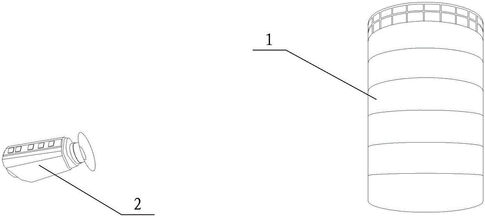
[0040] image 3 It is a schematic structural diagram of a liquid level measuring device provided by an embodiment of the present invention.
[0041] Such as image 3 As shown, the embodiment of the present invention also provides a liquid level measuring device, including: a monitor 2 arranged at a corresponding interval with the tank 1, and the monitor 2 is used to monitor the heat distribution field on the surface of the tank 1; The heat distribution field obtained by the instrument 2 determines the liquid level in the tank 1.
[0042] Compared with the prior art, the liquid level measuring device according to the embodiment of the present invention has the following advantages:
[0043] In the liquid level measuring device provided by the embodiment of the present invention, such as image 3 As shown, it includes: a monitor 2 arranged at intervals corresponding to the tank 1, and the monitor 2 is used to monitor the heat distribution field on the surface of the tank 1; during the measurement, the tank 1 is determined according to the heat distribution field obtained by the monitor 2 The height of the liquid level inside. From this analysis, it can be seen that when using the liquid level measuring device provided by the embodiment of the present invention, the monitor 2 can be used to monitor the heat distribution field on the surface of the tank 1, and then the corresponding heat distribution field obtained by the monitor 2 can be formed. Thermal image, and determine the liquid level in tank 1 according to the different temperatures represented by different colors on the thermal image (because the temperature of the liquid part in the tank is different from the temperature of the non-liquid part, it is reflected in the thermal image The color on the figure is also different); in addition, when the liquid level measuring device provided by the embodiment of the present invention is used, the monitor 2 provided outside the tank 1 is used for measurement, and there is no need to set up electronic products in the tank 1. At the same time, it is not necessary to open the tank 1 when measuring the liquid level, and the conversion method is avoided, but the tank 1 is effectively monitored and measured in real time. In summary, the liquid level measuring device provided by the embodiment of the present invention can effectively avoid the risk of leakage of the existing electronic liquid level gauge and cause explosion hazards such as oil tanks, and can effectively solve the indirect conversion method after long-term use. Technical problem of low accuracy when calculating liquid level height.
[0044] Among them, in order to better realize the monitoring of the thermal distribution field on the surface of the tank body 1, the above-mentioned monitor 2 may be a (infrared) thermal imager. Infrared thermal imaging camera uses infrared detectors and optical imaging objectives to receive the infrared radiation energy distribution pattern of the measured target and reflect it on the photosensitive element of the infrared detector to obtain an infrared thermal image. This thermal image is related to the heat on the surface of the object. The distribution field corresponds. In layman's terms, an infrared thermal imaging camera converts the invisible infrared energy emitted by an object into a visible thermal image. The different colors on the top of the thermal image represent different temperatures of the measured object.
[0045] Figure 4 It is a schematic structural diagram of another liquid level measuring device provided by an embodiment of the present invention.
[0046] In actual application, such as Figure 4 As shown, the liquid level measurement device provided by the embodiment of the present invention may further include: a processor 3, which is connected to the monitor 2 and can be used to calculate and determine the tank body 1 according to the heat distribution field obtained by the monitor 2 The height of the liquid level inside, so that the monitor 2 (ie, the thermal imager) can send the acquired thermal image of the thermal distribution field corresponding to the temperature information on the surface of the tank 1 to the processor 3, and the processor 3 can The situation shown in the thermal image of the thermal distribution field is converted into the liquid level height in the tank body 1, thereby effectively realizing the automatic measurement of the liquid level height of flammable and explosive oil tanks or oil-gas mixing tanks.
[0047] Wherein, the aforementioned processor 3 may be a computer. Computer, commonly known as computer, is a modern electronic computing machine used for high-speed calculations. It can perform numerical calculations, logical calculations, and storage and memory functions. It is a modern intelligent electronic device that can run in accordance with the program and process massive amounts of data automatically and at a high speed.
[0048] Optionally, the aforementioned processor 3 may also be a single-chip microcomputer. Microcontrollers (Microcontrollers) is a kind of integrated circuit chip, which uses VLSI technology to integrate the central processing unit CPU with data processing capabilities, random access memory RAM, read-only memory ROM, various I/O ports and interrupt systems, timers /Counter and other functions (may also include display drive circuit, pulse width modulation circuit, analog multiplexer, A/D converter and other circuits) integrated on a silicon chip to form a small and complete microcomputer system, in industry Widely used in the field of control. From the 1980s, from the then 4-bit and 8-bit single-chip microcomputers to the current 300M high-speed single-chip microcomputer.
[0049] Specifically, the separation distance between the monitor 2 and the tank 1 should be a safe distance; the safe distance is that the monitor 2 can clearly and completely obtain the heat distribution field on the surface of the tank 1, and even if the monitor 2 The blasting will not cause the tank 1 to explode.
[0050] Preferably, an isolation cover or the like can be provided on the outside of the monitor 2, so that the monitor 2 can be better protected by isolation devices such as isolation cover, and thereby effectively avoid the occurrence of the tank 1 caused by the explosion of the monitor 2 explosion.
[0051] Further, in order to avoid outdoor operation will be affected by weather and other reasons, such as Figure 4 As shown, both the monitor 2 and the processor 3 can be located indoors, as long as the window is opened to ensure that the monitor 2 can obtain the heat distribution field on the surface of the tank 1 well.
[0052] The embodiment of the present invention further provides a liquid level measurement system, which includes: a monitor 2 arranged toward a plurality of tanks 1, and the monitor 2 is used to monitor the heat distribution field on the surface of each tank 1; Processor 3: During the measurement, the processor 3 calculates and determines the liquid level height in each tank 1 according to the heat distribution field corresponding to each tank 1 obtained by the monitor 2. The liquid level measurement system provided by the embodiment of the present invention can not only effectively avoid the risk of leakage of the existing electronic level gauge and cause explosion hazards such as oil tanks, but also can effectively solve the indirect conversion method after long-term use. The technical problem of low accuracy in height calculation can also effectively realize the automatic measurement of the liquid level of flammable and explosive oil tanks or oil-gas mixing tanks.
[0053] Among them, in order to ensure that one monitor 2 can detect multiple tanks 1, the above-mentioned monitor 2 can be set on a turntable, so that the rotation of the turntable can drive the monitor 2 to turn, and then the multiple tanks arranged side by side at intervals 1 Monitor separately.
[0054] Optionally, the liquid level measurement system provided by the embodiment of the present invention includes: a plurality of monitors 2 arranged in a one-to-one correspondence with the plurality of tanks 1 at intervals, and the plurality of monitors 2 are used to monitor each tank 1 respectively. The heat distribution field on the surface; the processor 3 connected to multiple monitors 2; during measurement, the processor 3 calculates and determines each tank according to the heat distribution field corresponding to each tank 1 obtained by the multiple monitors 2 The height of the liquid level within 1.
[0055] It should be supplemented here that the liquid level measuring method, liquid level measuring device and system provided by the embodiments of the present invention are not limited to be applied only to flammable and explosive oil tanks or oil-gas mixing tanks, etc. The measurement can also be applied to any other tanks or devices that need to measure the height of the liquid level.
[0056] In the liquid level measuring method, liquid level measuring device and system provided by the embodiments of the present invention, the core technical point is: the liquid level height measurement is performed by a monitor such as a thermal imager. Since the temperature of the liquid part in the tank is different from the temperature of the non-liquid part, the color reflected on the thermal image is also different. This situation can be summarized as the principle of imbalance: due to the difference in composition and material (or inclusions) of various parts of the object, when interacting with the outside world, the corresponding parts of the object will react differently (different degree of response) ). According to the present invention, when the lower part of the liquid container tank and the upper part without liquid interact with the outside temperature, the non-liquid part and the liquid part will produce a temperature difference on the surface of the tank (that is, the temperature of the tank is unbalanced), As long as there is an imbalance between the tank body and the outside temperature (that is, there is a temperature difference), the tank body will continue to be unbalanced. Corresponding to the outdoor tank body, because the outdoor temperature is always changing, the tank body always interacts with the outside world. Therefore, the tank is always in a state of temperature imbalance.
[0057] The above descriptions are only preferred embodiments of the present invention and are not intended to limit the present invention. Any modification, equivalent replacement, improvement, etc. made within the spirit and principle of the present invention shall be included in the present invention. Within the scope of protection.
PUM


Description & Claims & Application Information
We can also present the details of the Description, Claims and Application information to help users get a comprehensive understanding of the technical details of the patent, such as background art, summary of invention, brief description of drawings, description of embodiments, and other original content. On the other hand, users can also determine the specific scope of protection of the technology through the list of claims; as well as understand the changes in the life cycle of the technology with the presentation of the patent timeline. Login to view more.