
Nondestructive inspection device for wire rope

A non-destructive testing and wire rope technology, applied in the direction of material magnetic variables, etc., can solve the problems of missed judgment, confusion of other signals of MFL signals, interference of MFL signals, etc., and achieve the effect of improving the signal-to-noise ratio.

Inactive Publication Date: 2017-06-13
LANZHOU INST OF PHYSICS CHINESE ACADEMY OF SPACE TECH
View PDF6 Cites 12 Cited by
  • Summary
  • Abstract
  • Description
  • Claims
  • Application Information

AI Technical Summary

Problems solved by technology

[0005] At present, there is a problem with the non-destructive testing method of steel wire rope by detecting the magnetic flux leakage signal: compared with the background magnetic signal of the steel wire rope, the magnetic flux leakage signal is very weak, and there is a strand wave in the steel wire rope itself, which interferes with the magnetic flux leakage signal, so the magnetic flux leakage signal It is easy to be confused or overwhelmed by other signals, resulting in missed and misjudgment

Method used


Image

  • Nondestructive inspection device for wire rope
  • Nondestructive inspection device for wire rope
  • Nondestructive inspection device for wire rope

Examples


Embodiment Construction

[0027] The present invention will be described in detail below with reference to the accompanying drawings and examples.

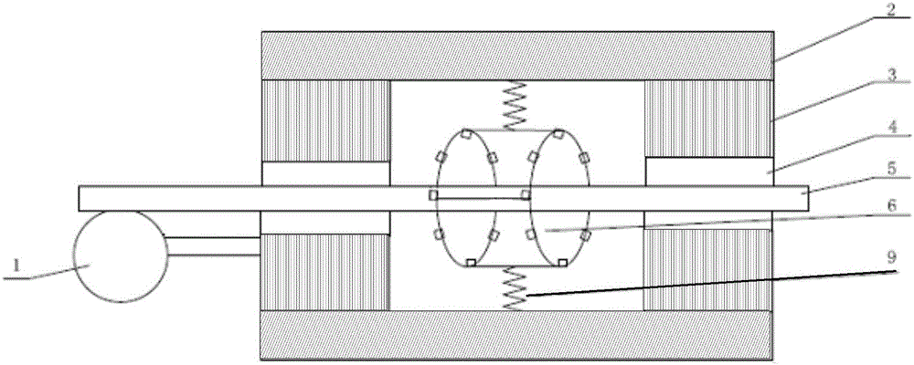
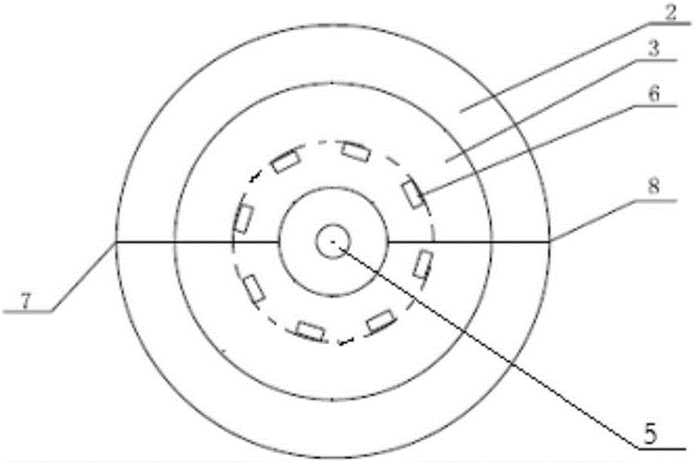
[0028] Fig. 2(a) and Fig. 2(b) are schematic diagrams of the principles of the non-destructive testing device for steel wire ropes of the present invention. As shown in the figure, the device includes: an excitation component, a sensor component, a data processing module and an angle encoder 1 .

[0029] The excitation assembly is used to provide a uniform magnetic field. In this embodiment, the excitation assembly is composed of a cylindrical magnetic conductor 2 and two annular permanent magnets 3 . Wherein, the cylindrical magnetizer 2 is made of industrial pure iron, and the annular permanent magnet 3 is made of permanent magnets. Two annular permanent magnets 3 are installed at both ends of the inner wall of the cylindrical magnetizer 2 , and an air gap 4 is provided in the middle of the annular permanent magnets 3 . The steel wire rope 5 passes th...


PUM


Abstract

The invention discloses a nondestructive inspection device for a wire rope. In addition to an excitation component, a sensor component and a data processing module, the nondestructive inspection device also comprises an angle encoder, wherein the sensor component is a sensor differential array composed of n pairs of sensors; the n pairs of sensors are distributed on two rings having equal radii; the axes of the two rings coincide; the distance between the two rings is a strand wave period length of a wire rope; the sensors on each ring are distributed at equal angles; the sensors belonging to one pair are distributed on the same angle positions of the two rings; the sensor differential array is positioned in the excitation component; the wire rope to be inspected is penetrated through the sensor differential array and is in contact with a roller wheel of the angle encoder; the data processing module performs differential operation on collection signals of each pair of sensors to obtain n differential results; and if a peak exists among the differential results, the wire rope is considered as having a damage defect. According to the invention, strand wave noise interference can be effectively eliminated.

Description

technical field [0001] The invention belongs to the field of nondestructive testing, in particular to a nondestructive testing device for steel wire ropes. Background technique [0002] Steel wire rope is widely used as a key component for lifting, transporting and bearing the weight of equipment due to its many advantages such as high strength, light weight, good elasticity, stable and reliable operation, and can run under high-speed working conditions. During the long-term operation of the steel wire rope, affected by environmental corrosion, uncertain alternating loads, mechanical shock, wear, etc., there will be damages such as broken wires, abrasion, corrosion, etc., which will lead to a decrease in the strength of the steel wire rope or even a sudden break over time. If it stops, the machine will be destroyed and people will die. [0003] There are many non-destructive testing methods for steel wire ropes that have been discussed in theory. At present, only the electr...

Claims


Application Information

Patent Timeline
IPC IPC(8): G01N27/83
Inventor 文轩郑阔海杨生胜苗育君秦晓刚
Owner LANZHOU INST OF PHYSICS CHINESE ACADEMY OF SPACE TECH
Learn More