Simulation test device for debris flow and test method

A technology for simulating test and debris flow, applied in soil material testing, material inspection products, etc., can solve problems such as inability to carry out continuous experiments, and achieve the effect of facilitating observation and collection of experimental data

Pending Publication Date: 2017-06-13
NORTHWEST RES INST CO LTD OF C R E C
View PDF6 Cites 24 Cited by
  • Summary
  • Abstract
  • Description
  • Claims
  • Application Information

AI Technical Summary

Problems solved by technology

[0004] The purpose of the present invention is to provide a debris flow simulation test device to solve t

Method used


Image

  • Simulation test device for debris flow and test method
  • Simulation test device for debris flow and test method
  • Simulation test device for debris flow and test method

Examples


Embodiment 1

[0043] Embodiment 1-debris flow simulation test method:

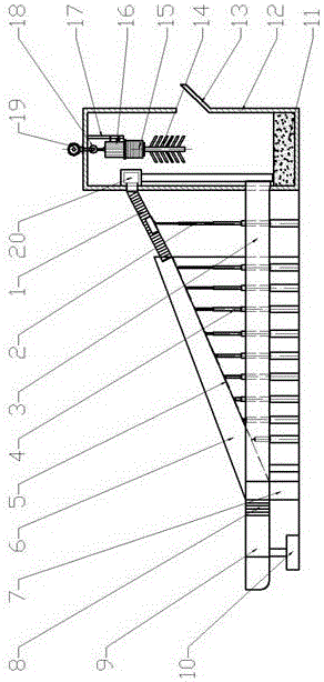
[0044] Add the debris flow mixture 11 into the bucket 12 through the feed port 13, operate the control panel 22, start the stirring system, descend and stir the mixture 11, and after making it uniform, the stirring system is raised by operating the control panel 22, and then through the control panel 22 Start the turbo pump 20, transport the debris flow mixture to the designated height to start the experiment, and collect the experimental data and patterns. Stirring system and turbo pump 20 can choose to work simultaneously or can choose to work alone, and the two cooperate with each other to work independently. During the experiment, the debris flow mixture 11 continuously enters the bucket 12 through the horizontal chute 3 to be recycled.

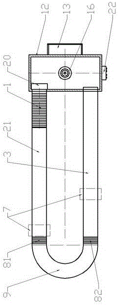
[0045] image 3 It shows a schematic diagram of a debris flow simulation test device in the adjustment state of the inclined chute. Turning the stud bolt 28 can realize the direc...

Embodiment 2

[0047] Embodiment 2-debris flow simulation test method:

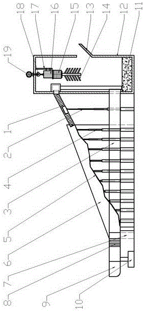
[0048] Figure 4 Shows a state diagram in which the inclined chute is in the horizontal plane in the debris flow simulation test device, changing the height of the hydraulic jack group and the length of the slope adjustment screw 28 can reach a position close to the horizontal position, so as to be used for studying the horizontal position. natural flow under action. During the experiment, the debris flow mixture 11 continuously enters the bucket 12 through the horizontal chute 3 to be recycled.

Embodiment 3

[0049] Embodiment 3-barrier test:

[0050] When there is no need to study the impact force and information collection of the debris flow, the connection cover 24 and the connection cover 25 are all in a horizontal position, and the debris flow flows through it; Debris flow interception, simulation of the impact force during the flow of debris flow, observation and extraction of experimental data and collection of patterns.


PUM


Abstract

The invention discloses a simulation test device for debris flow and a test method and belongs to the field of debris flow simulation test, in order to solve the problem that the present simulation test device for debris flow cannot continuously experiment. The simulation test device for debris flow comprises a charging basket, a runner, a lifting system and a stirring system, wherein the stirring system is arranged at the top of the charging basket; the device further comprises a control panel, a hydraulic system and a lateral baffle; a turbine pump is arranged on the middle part of an inner wall of the charging basket; the hydraulic system comprises a hydraulic cylinder and a hydraulic jack set; the runner is formed by connecting an inclined chute, a semicircular arc slot and a horizontal chute; the hydraulic jack set is supported under the inclined chute; the bottom of an extension pipe is supported by the hydraulic cylinder. According to the invention, the inclined chute is supported by the hydraulic jack; the combination of the arc chute and the inclined chute can realize the adjustment for the gradient of the inclined chute; the debris flow effects at different gradients can be simulated.

Description

technical field [0001] The invention belongs to the field of mud-rock flow simulation test, and in particular relates to a mud-rock flow simulation test device. Background technique [0002] As we all know, the existing debris flow experimental systems and equipment are classified into two types: one is the form of inclined chute, and its disadvantages are: the test observation time is extremely short, the experiment cannot be carried out continuously, and the debris flow solid material required during the experiment And water needs to be transported to a certain height, the workload is heavy, and the test takes a long time. The other is an annular water tank type. Although this method can achieve continuous observation of the test, it cannot be used because most of the annular equipment used will generate a large centrifugal force when rotating, and most of them use plexiglass and use a cyclotron. Simulating the flow trajectory of the debris flow will distort the final tes...

Claims


Application Information

Patent Timeline
IPC IPC(8): G01N33/24
CPCG01N33/24
Inventor 吴红刚董占林陈小云冯文强熊治文张俊德宋响军赖国泉李元彪庞伟军常刚张乾翼任庆钊李菊芳冯帅
Owner NORTHWEST RES INST CO LTD OF C R E C
Why Eureka
Try Eureka