Bistatic synthetic aperture radar imaging method and device

A technology of synthetic aperture radar and imaging method, applied in measurement devices, radio wave reflection/re-radiation, utilization of re-radiation, etc., can solve the problem that the frequency domain imaging algorithm cannot adapt, the focusing process takes a long time, and the time domain imaging algorithm is complicated. high degree issues

Inactive Publication Date: 2017-06-13
INST OF ELECTRONICS CHINESE ACAD OF SCI
View PDF4 Cites 9 Cited by
  • Summary
  • Abstract
  • Description
  • Claims
  • Application Information

AI Technical Summary

Problems solved by technology

[0004] Focusing algorithms for BiSAR data include time-domain imaging algorithms and frequency-domain imaging algorithms. The time-domain imaging method is suitable for the above three BiSAR modes and has the best focusing quality; however, it is different from frequency-domain imaging algorithms such as distance Compared with the Range Doppler Algorithm (RDA) and the Nonlinear Chirp Scaling Algorithm (NLCSA), the time-domain imaging algorithm has high time complexity and the focusing process takes a long time; while the frequency-domain imaging algorithm cannot adapt to The above three BiSAR modes

Method used


Image

  • Bistatic synthetic aperture radar imaging method and device
  • Bistatic synthetic aperture radar imaging method and device
  • Bistatic synthetic aperture radar imaging method and device

Examples


Embodiment 1

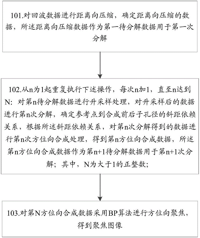
[0046] figure 1 The implementation process of the method for BiSAR imaging in the embodiment of the present invention includes the following steps:

[0047] Step 101: performing range compression on the echo data, and determining the range compressed data, which is used as the first data to be decomposed for the first decomposition.

[0048] In this step, according to the different modes of BiSAR imaging, the echo data can be compressed in the range direction through the matched filter, and the data compressed in the range direction can be determined; specifically include:

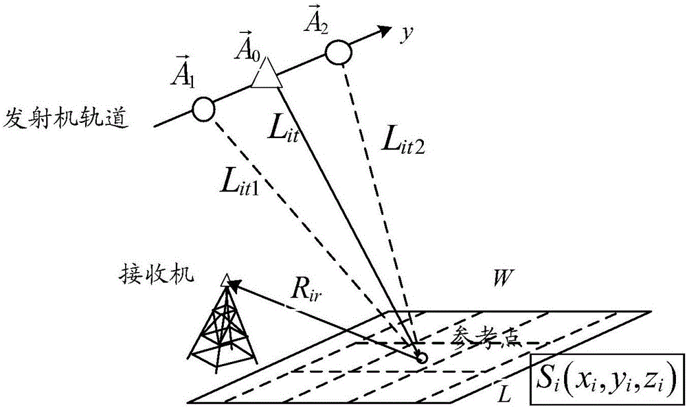
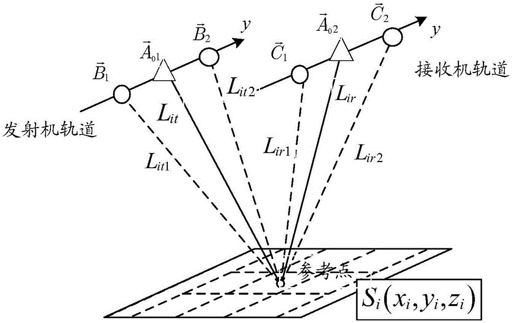
[0049] When the echo data is azimuth-displacement-invariant BiSAR data, the echo data is subjected to Fourier forward transform first, then multiplied by the frequency-domain matched filter function, and then inverse Fourier transform is performed to obtain range-compressed data;

[0050] When the echo data is one-station fixed BiSAR data, first perform Fourier forward transform on the echo data, and then...

Embodiment 2

[0137] In order to implement the method of Embodiment 1, the BiSAR imaging device provided by the embodiment of the present invention, such as Figure 4 As shown, the device includes: a range compression module 41, an azimuth synthesis module 42, and an azimuth focus module 43, wherein,

[0138] The range compression module 41 is configured to perform range compression on the echo data, and determine the range compressed data, and the range compression data is used as the first data to be decomposed for the first decomposition;

[0139] The azimuth synthesis module 42 is used to repeatedly perform the following operations since n is 1, adding 1 to n each time until n reaches N: perform up-sampling processing on the nth data to be decomposed, and perform up-sampling processing on the up-sampled data Decomposition for the nth time determines the slant distance dependence relationship between the reference point and the sub-aperture before and after synthesis, and according to th...


PUM


Abstract

The invention discloses a bistatic synthetic aperture radar imaging method (BiSAR) imaging method. Echo data is subjected to range direction compression, data of range direction compression is determined, and the data of range direction compression serves as first to-be-decomposed data for first decomposition; following operation is repeatedly executed starting from n being 1, 1 is added to n every time till n reaches N, n to-be-decomposed data is subjected to upsampling processing, the upsampled data is subjected to n decomposition, the slant range dependence relationship between a reference point and a synthetic front sub-aperture and a synthetic rear sub-aperture is determined, data obtained after n decomposition is subjected to n azimuth direction synthetic processing according to the slant range dependence relationship, n azimuth direction synthetic data is obtained, and the n azimuth direction synthetic data serves as (n+1) to-be-decomposed data for (n+1) decomposition, wherein N is a positive integer larger than 1; N azimuth direction synthetic data is subjected to azimuth direction focusing through a back projection (BP) algorithm, and focusing images are obtained. The invention further discloses a BiSAR imaging device.

Description

technical field [0001] The present invention relates to a synthetic aperture radar (Synthetic Aperture Radar, SAR) technology, in particular to a bistatic synthetic aperture radar (Bistatic Synthetic Aperture Radar, BiSAR) imaging method and device. Background technique [0002] BiSAR is a SAR imaging system in which the receiver and transmitter are located on different working platforms, and there is a certain spatial baseline between the receiver system and the transmitter system. Due to the separation of transceivers, the BiSAR system has advantages that traditional single-base SAR does not have: firstly, the transceiver system is separated, and the configuration of "one send, multiple collection" can be realized at a lower hardware cost; secondly, the platform on which the transmitter and receiver are equipped Diversified to form different bi-base imaging systems, for example: take the on-orbit spaceborne SAR as the transmitting source, use the airborne platform to form ...

Claims


Application Information

Patent Timeline
Patent Type & Authority Applications(China)
IPC IPC(8): G01S13/90G01S7/41
CPCG01S13/904G01S7/41G01S13/9058G01S13/9017G01S13/003
Inventor 张衡邓云凯王宇唐江文王吉利李宁周春晖
Owner INST OF ELECTRONICS CHINESE ACAD OF SCI
Why Eureka
Try Eureka