Test box for electronic communication teaching

A test box and electronic technology, applied in the field of test boxes, can solve the problems of lack of communication-related courses and experimental platforms, and achieve the effect of simple structure

Pending Publication Date: 2017-06-13
HENAN NORMAL UNIV
6 Cites 2 Cited by

AI-Extracted Technical Summary

Problems solved by technology

For courses such as communication principles that need to link theory and practice, corresponding experimental teaching aids are needed as the carrier o...

Method used

Principle of work: coded lock 3 is installed between the case lid 2 of this kind of test box and casing 1, the inside of casing 1 is provided with the first placement groove 7 and the second placement groove 8 by dividing plate 6, the second placement groove 8 The inside of the first placement slot 7 is provided with a host 12 and a plug-in strip 9, the inside of the host 12 is provided with a video capture card 13, and the inside of the second placement slot 8 is provided with an ammeter 21, and the positive and negative poles of the ammeter 21 are connected to the conductor 22 through a ...

Abstract

The invention discloses a test box for electronic communication teaching. A password lock is mounted between a box body and a box cover; four containing bags are arranged at the inner side of the box cover; the inner part of the box body is separated into a first placement groove and a second placement groove through a separation plate; a power strip is arranged in the first placement groove; one end of the power strip is connected with an electric wire plug; the electric wire plug is exposed into an external environment of the box body through a through hole; a host is further arranged in the first placement groove; a video acquisition card is mounted in the host; a display screen is arranged at the top of the host; one side of the host is connected with a monitoring camera through a video signal wire; an ammeter is arranged in the second placement groove; positive and negative electrodes of the ammeter are connected with a conductor through lead wires. By adopting the test box disclosed by the invention, an electromagnet can be used for carrying out electromagnetic induction experiments; when the electromagnetic induction experiments are carried out, the monitoring camera is used for monitoring the reading displayed by the ammeter and transmitting a monitored picture to the video acquisition card; the monitored picture is displayed through the display screen of the host.

Application Domain

Educational models

Technology Topic

Electronic communicationSurveillance camera +10

Image

  • Test box for electronic communication teaching
  • Test box for electronic communication teaching

Examples

  • Experimental program(1)

Example Embodiment

[0015] The technical solutions in the embodiments of the present invention will be clearly and completely described below in conjunction with the accompanying drawings in the embodiments of the present invention. Obviously, the described embodiments are only a part of the embodiments of the present invention, rather than all the embodiments. Based on the embodiments of the present invention, all other embodiments obtained by those of ordinary skill in the art without creative work shall fall within the protection scope of the present invention.
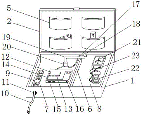
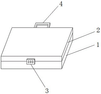
[0016] See Figure 1-2 , The present invention provides a technical solution: a test box for electronic communication teaching, including a box body 1, a box cover 2, a code lock 3, a handle 4, a receiving bag 5, a partition 6, a first placement slot 7, a second Placement slot 8, power strip 9, wire plug 10, through hole 11, host 12, video capture card 13, display 14, USB port 15, power jack 16, video signal line 17, surveillance camera 18, fixed pole 19. Mounting base 20, ammeter 21, conductor 22 and wire 23. One side of box body 1 is provided with box cover 2, a code lock 3 is installed between box body 1 and box cover 2, and the other side of box body 1 is installed There is a handle 4, the inner side of the box cover 2 is provided with four holding bags 5, the inside of the box body 1 is divided into a first placing groove 7 and a second placing groove 8 by a partition 6, and the inside of the first placing groove 7 is placed Row 9, one end of the plug-in row 9 is connected with a wire plug 10, the wire plug 10 is exposed to the external environment of the box 1 through the through hole 11, and the host 12 is also placed in the first placement slot 7, and the video is installed inside the host 12 Capture card 13, a display screen 14 is provided on the top of the host 12, a USB port 15 and a power jack 16 are provided on one side of the host 12, and a surveillance camera 18 is connected to one side of the host 12 through a video signal line 17. An ammeter 21 is placed inside the slot 8, and the positive and negative electrodes of the ammeter 21 are connected to the conductor 22 through a wire 23.
[0017] Further, the surveillance camera 18 is installed on the top of the mounting seat 20 via a fixed rod 19, which is convenient for use.
[0018] Further, a host power adapter and a magnet are contained in the containing bag 5, the host power adapter is used to supply power to the host, and the magnet is used to perform magnetic field cutting to generate electrical energy.
[0019] Further, the host 12 is electrically connected to the surveillance camera 18 through the video signal line 17, the surveillance camera 18 is electrically connected to the video capture card 13, the video capture card 13 is electrically connected to the display 14, and the surveillance camera 18 transmits the monitoring screen of the ammeter 21 to The video capture card 13 and the information collected by the video capture card 13 are displayed on the display screen 14.
[0020] Further, the monitoring camera 18 is fixedly installed at the end of the fixed rod 18 by fastening screws, and is used to monitor the reading of the ammeter 21.
[0021] Working principle: A code lock 3 is installed between the lid 2 and the box body 1 of this kind of test box. The inside of the box body 1 is provided with a first placement groove 7 and a second placement groove 8 through the partition plate 6. The first placement groove 7 is provided with a host 12 and a plug-in strip 9 inside. The inside of the host 12 is provided with a video capture card 13, and the inside of the second placement slot 8 is provided with an ammeter 21. The positive and negative electrodes of the ammeter 21 are connected to the conductor 22 through a wire 23. In the electromagnetic induction experiment, a magnet can be used for magnetic induction cutting to generate electric energy. During electromagnetic induction, the monitoring camera 18 monitors the display of the ammeter 21, and the monitored picture is transmitted to the video capture card 13 and displayed on the display screen 14. Come out, this kind of test box is very convenient when conducting electronic communication experiments.
[0022] Although the embodiments of the present invention have been shown and described, those of ordinary skill in the art can understand that various changes, modifications, and substitutions can be made to these embodiments without departing from the principle and spirit of the present invention. And variations, the scope of the present invention is defined by the appended claims and their equivalents.

PUM

no PUM

Description & Claims & Application Information

We can also present the details of the Description, Claims and Application information to help users get a comprehensive understanding of the technical details of the patent, such as background art, summary of invention, brief description of drawings, description of embodiments, and other original content. On the other hand, users can also determine the specific scope of protection of the technology through the list of claims; as well as understand the changes in the life cycle of the technology with the presentation of the patent timeline. Login to view more.

Similar technology patents

Body condition measuring device

InactiveUS20050234351A1simple structure
Owner:DENSO CORP

Magnetic cooling apparatus and control method thereof

ActiveUS20130180263A1simple structure
Owner:SAMSUNG ELECTRONICS CO LTD

Dual-Drivetrain of Power-Assist Vehicle

InactiveUS20100181130A1enhance uphill momentumsimple structure
Owner:CHOU WEN CHENG

Classification and recommendation of technical efficacy words

  • Simple structure

Sharing system for air-conditioning coat

InactiveCN107440179ASimple structureeasy to wear
Owner:QINGDAO HAIER AIR CONDITIONER GENERAL CORP LTD

Feeding device of sorter of batteries plate

InactiveCN101357717ASimple structurecooperate well
Owner:NANJING NORMAL UNIVERSITY

Emergency parachuting device and method for multiple-rotor unmanned aerial vehicle

InactiveCN103895870Aavoid aircraft crashSimple structure
Owner:SOUTH CHINA AGRI UNIV +1
Why Eureka
Try Eureka