Automatic wire harness machine

A technology of automatic line and main motor, applied in the direction of electrical components, circuits, conductor/cable insulation, etc., to achieve precise assembly, efficient assembly work, and reduce labor requirements

Inactive Publication Date: 2017-06-13
李星明
View PDF2 Cites 1 Cited by
  • Summary
  • Abstract
  • Description
  • Claims
  • Application Information

AI Technical Summary

Problems solved by technology

[0009] The purpose of the present invention is to provide an automatic wire harness machine, which solves the problem of the automatic winding method of the wire harness winding technology in the wire harness processing and assembly process, and accurately adjusts the winding process of the wire harness to make the winding uniform, fast, and human-friendly. Less physical exertion, time-saving and labor-saving, accurate wire harness automatic winding assembly

Method used


Image

  • Automatic wire harness machine

Examples


Embodiment 1

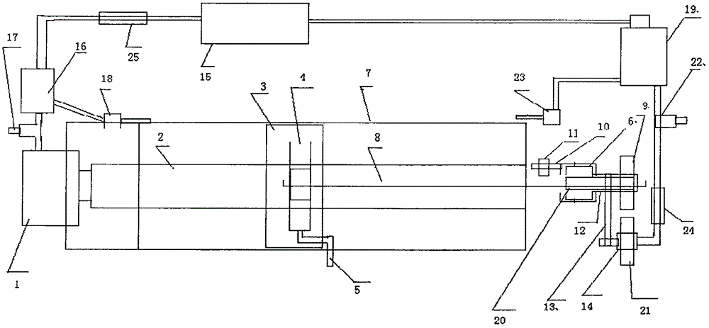
[0017] When the winding work has not yet started, the main switch 25 is turned off, and the traction block 3 is located at the rear end of the base 7. At this time, one end of the wire harness 8 to be processed is firstly wound with the tape roll 11 twice, and then passed through the fixing sleeve 20. Install the hole forward on the wire clamping vise 4, turn the crank 5 to clamp the wire harness, install the tape roll 11 on the tape seat 10, draw out a certain length of tape, and wrap it twice on the corresponding position of the wire harness to be processed. , turn on the auxiliary motor steering and stop switch 24, and then turn on the main switch 25. At this time, the main motor 1 and the auxiliary motor start to work, and the main motor drives the traction block 3, the clamping vise 4 and the wire harness 8 to be processed to move forward, and at the same time The auxiliary motor 21 drives the pulley 12 through the belt 13 to rotate the sleeve 6, the tape seat 10 and the t...

Embodiment 2

[0020] At the beginning of this stroke, the traction block 3 and the wire clamping vise 4 are at the front end of the base, turn on the main switch 25 and the main motor 1 starts to rotate, the traction block 3 and the wire clamping vise 4 move to the rear end of the base, at this time the auxiliary The motor and the wire harness 8 to be processed are in a stopped state. When the traction block 3 and the wire clamping vise 4 move to the sensing range of the rear travel switch 23 at the rear end of the base, the rear travel switch 23 sends a steering signal to the main motor controller 16. The main motor 1 starts to rotate in the forward direction. At this time, the main switch of the circuit needs to be turned off, so that the main and auxiliary motors all stop rotating. This time the return stroke is over.

Embodiment 3

[0022] At the beginning of this stroke, the traction block 3 is at the rear end of the base 7. At this time, it is necessary to install the wire harness 8 that needs to be processed beside it on the wire clamping vise, rotate the crank 5 to clamp the wire harness and fix it, turn on the auxiliary motor steering And stop switch 24, then turn on the main switch 25, at this time the main motor 1 and the screw shaft 2 start to rotate, driving the traction block 3 and the wire harness 8 to be processed to move forward, and the auxiliary motor 21 starts to work, driving the pulley through the belt 13. 12. The rotating sleeve 6, the tape base 10 and the tape roll 11 rotate around the wire harness 8 to be processed, and the next working stroke starts, and so on and so forth.

[0023] In particular, the speed adjustment switches of the main and auxiliary motors can be adjusted only once under normal circumstances. When the winding speed is found to be too fast or too slow, and the windi...


PUM


Abstract

The invention discloses an automatic wire harness machine. The basic structure includes a base, a power supply, a stroke traction part and a working part. The invention solves the automation problem of the winding process in the wire harness processing process, and can solve the complex winding process in the wire harness production process. Simplify, and can greatly reduce the heavy physical labor and workload in the production process of wire harness winding, so that the original wire winding work in the wire harness production line has changed from manual operation to machine operation, to a greater extent Reduce labor requirements, reduce production costs, improve production efficiency and product quality.

Description

technical field [0001] The invention belongs to the technical field of electromechanical integration, and in particular relates to an automatic wire harness machine, which is suitable for wire harness processing and assembly and related products. Background technique [0002] With the development of the electronic and information age, the wire harness industry has been known as the "nerve" and "vessel" of the city, shouldering the supporting functions of the pillar industries of the national economy in all walks of life. Wire harnesses have been used in the fields of automobiles, home appliances, computers, communication equipment, military, and aviation instruments. In recent years, some wire tape winding machines have appeared one after another. The tape winding machine with the number of CN 103332319 B is designed for the shortcomings of a semi-automatic tape winding machine disclosed in the utility model patent with the publication number of CN202268216U, including a fra...

Claims


Application Information

Patent Timeline
Patent Type & Authority Applications(China)
IPC IPC(8): H01B13/08
CPCH01B13/0816
Inventor 李成城
Owner 李星明
Why Eureka
Try Eureka