Supercharge Your Innovation With Domain-Expert AI Agents!

Passive plasma lightning expeller

A plasma and lightning arrester technology, applied in electrical components, circuits, corona discharge devices, etc., can solve the problems of lightning strikes, insufficient lightning clearance, and high failure probability of lightning clearance, so as to protect buildings, weaken the thunder cloud effect

Inactive Publication Date: 2017-06-13
宁夏顺和电工有限公司
View PDF7 Cites 4 Cited by
  • Summary
  • Abstract
  • Description
  • Claims
  • Application Information

AI Technical Summary

Problems solved by technology

[0006] The dissipative array (DAS) generates plasma under the action of the thundercloud electric field to neutralize the thundercloud charge. Due to the self-assessment avoidance effect, the plasma generated is far from sufficient for lightning elimination, resulting in a high probability of failure in lightning elimination, especially through Semiconductor lightning suppressors with insufficient flow are often destroyed by lightning

Method used


Image

  • Passive plasma lightning expeller
  • Passive plasma lightning expeller

Examples


Embodiment 1

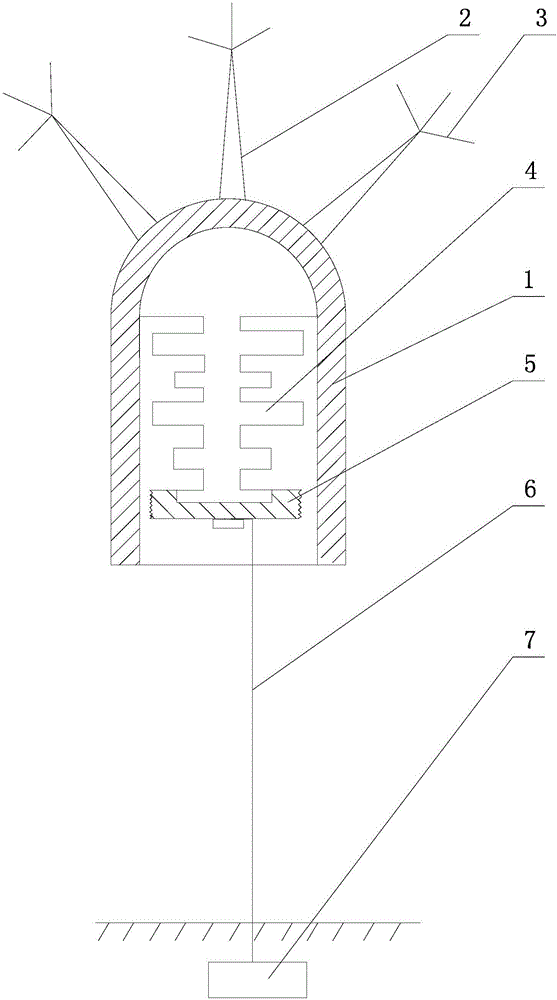
[0027] Such as figure 1 As shown, a passive plasma lightning drive device includes a metal cover 1, a plurality of discharge needles 2 are uniformly arranged on the outer wall of the metal cover 1, and a plurality of first-stage discharge needles 3 are arranged at the end of the discharge needle 2, and the inner wall of the opening end of the metal cover 1 is installed There is an insulator 4, the bottom of the insulator 4 is provided with an electrode 5, and the electrode 5 is spaced from the inner wall of the metal cover 1, and the electrode 5 is connected to the earth through the ground wire 6. By designing the metal cover 1, the discharge needle 2, the primary discharge needle 3 and The electrode 5 realizes that under the action of the thundercloud electric field, the primary discharge needle 3 and the thundercloud generate a passive primary discharge, and a passive secondary discharge is generated between the metal cover 1 and the electrode 5, and a large amount of plasma ...

Embodiment 2

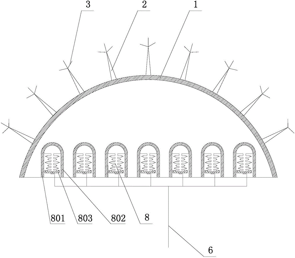
[0032] Such as figure 2 As shown, a single or multiple plasma generating chambers 8 are arranged inside the metal housing 1 , and a number of discharge needles 2 are uniformly arranged on the outer wall of the metal housing 1 .

[0033] A number of primary discharge needles 3 are arranged at the end of the discharge needle 2 .

[0034] The plasma generating chamber 8 includes a first metal outer cover 801, a first insulator 802 is installed on the inner wall of the opening end of the first metal outer cover 801, and a first electrode 803 is arranged at the bottom of the first insulator 802. The first electrodes 803 are arranged at intervals, and the first electrodes 803 are connected to the ground through the ground wire 6 to increase the amount of plasma generated.

[0035] The first metal housing 801 is connected to the metal housing 1 through wires

[0036] Embodiment 1 is example, illustrates the course of work of the present invention:

[0037] When there is thundercl...


PUM


Abstract

The invention relates to a passive plasma lightning expeller. The passive plasma lightning expeller comprises a metal outer cover, wherein a plurality of discharge needles are uniformly arranged at the outer wall of the metal outer cover; an insulator is arranged at the inner wall of the opening end of the metal outer cover, an electrode is arranged at the bottom part of the insulator, a separating device is arranged between the electrode and the inner wall of the metal outer cover, and the electrode is connected with ground through a grounding line. The passive plasma lightning expeller has the advantages that by arranging the metal outer cover, the discharge needles, primary discharge needles and the electrode, under the action of a lightning cloud electric field, the primary discharge needles and the lightning cloud can produce passive primary discharge, and the metal outer cover and the electrode produce passive secondary discharge, so that a large amount of plasmas is produced by two stages of discharge; positive ions drift to the lightning cloud, the negative charges in the lightning cloud are neutralized, and then the lightning cloud is weakened, so as to protect buildings.

Description

[0001] Technical field: [0002] The invention relates to the technical field of lightning protection, in particular to a passive plasma lightning drive. [0003] Background technique: [0004] For more than 260 years, the international lightning protection community has mainly used the lightning rod (lightning receptor) invented by Franklin, which attracts the thundercloud electric field to concentrate on its metal needle and increases the electric field intensity at the needle end, so that the thundercloud electric field breaks down the metal needle and will be strong. The lightning current leaks into the ground through its grounding body, which brings negative hazards such as counterattack, step voltage, connection voltage, and electromagnetic pulse induced overvoltage damage to the strong and weak current system. [0005] The early discharge lightning arrester (ESE) of the same lightning receiving mechanism attracts more lightning side strikes and shielding strikes, which i...

Claims


Application Information

Patent Timeline
IPC IPC(8): H01T19/04
CPCH01T19/04
Inventor 李先举李先众李世伟姚春林申玉超
Owner 宁夏顺和电工有限公司
Features
  • R&D
  • Intellectual Property
  • Life Sciences
  • Materials
  • Tech Scout
  • Unparalleled Data Quality
  • Higher Quality Content
  • 60% Fewer Hallucinations
Learn More