Abnormality detecting device of electric power converting device and abnormality detecting method

a technology of abnormality detection and abnormality detection, which is applied in the direction of power supply testing, lighting and heating apparatus, instruments, etc., can solve the problem of inability to accurately determine and achieve the effect of accurately determining the shorted faulty switching elemen

Active Publication Date: 2009-01-08
DENSO CORP
View PDF6 Cites 60 Cited by
  • Summary
  • Abstract
  • Description
  • Claims
  • Application Information

AI Technical Summary

Benefits of technology

[0015]An object of the invention is to provide an abnormality detecting device of an electric power converting device that can accurately determine a shorted faulty switching element.

Problems solved by technology

Therefore, it is impossible to accurately determine the shorted faulty switching element from a result of the detection of the overcurrent.

Method used


Image

  • Abnormality detecting device of electric power converting device and abnormality detecting method
  • Abnormality detecting device of electric power converting device and abnormality detecting method
  • Abnormality detecting device of electric power converting device and abnormality detecting method

Examples


first embodiment

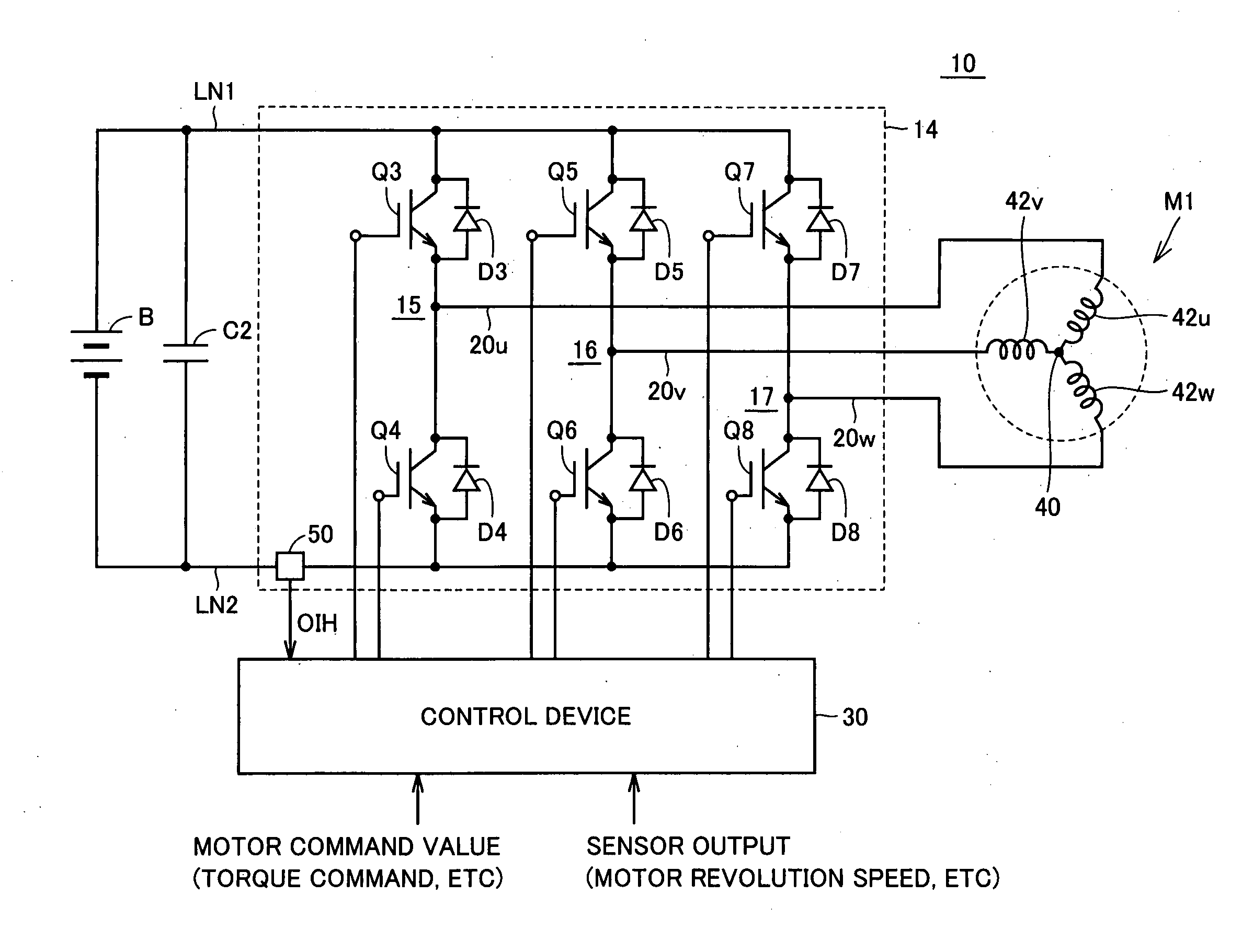
[0046]FIG. 1 is a circuit diagram showing a whole structure of a power supply system according to a first embodiment of the invention.

[0047]Referring to FIG. 1, a power supply system 10 includes a battery B that is a DC power supply, an inverter 14, a capacitor C2, a three-phase AC motor M1 and a control device 30.

[0048]Battery B has a positive electrode connected to a power supply line LN1 and a negative electrode connected to a ground line LN2. Battery B is a chargeable and dischargeable secondary battery, and is formed of, e.g., a nickel hydrogen battery or a lithium ion battery. Battery B may be replaced with a chargeable and dischargeable electricity accumulating device such as a capacitor other than the secondary battery.

[0049]Capacitor C2 is connected between power supply line LN1 and ground line LN2, and reduces an influence exerted on inverter 14 due to voltage variations.

[0050]Three-phase inverter 14 that is described as a typical example of the “electric power converting ...

second embodiment

[0083]FIG. 5 is a circuit diagram showing a whole structure of a power supply system according to a second embodiment of the invention.

[0084]A power supply system 10A in FIG. 5 additionally includes a converter 12 that is a “voltage converter” between battery B and capacitor C2 in power supply system 10 in FIG. 1. Therefore, detailed description of the same portions as those in FIG. 1 will not be repeated.

[0085]Converter 12 boosts the DC voltage supplied from battery B, and supplies it to capacitor C2. Also, converter 12 steps down the DC voltage supplied from inverter 14 via capacitor C2, and supplies it to battery B.

[0086]More specifically, converter 12 is formed of, e.g., a step-up / down chopper circuit, and includes a reactor L1, switching elements Q1 and Q2, and diodes D1 and D2.

[0087]One end of reactor L1 is connected to the power supply line of battery B, and the other end thereof is connected to an intermediate point between switching elements Q1 and Q2, i.e., a point between...

third embodiment

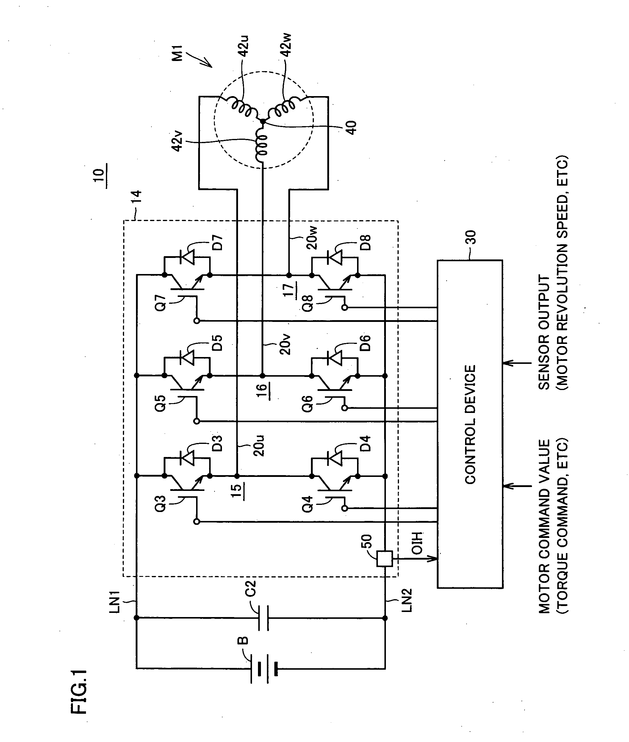
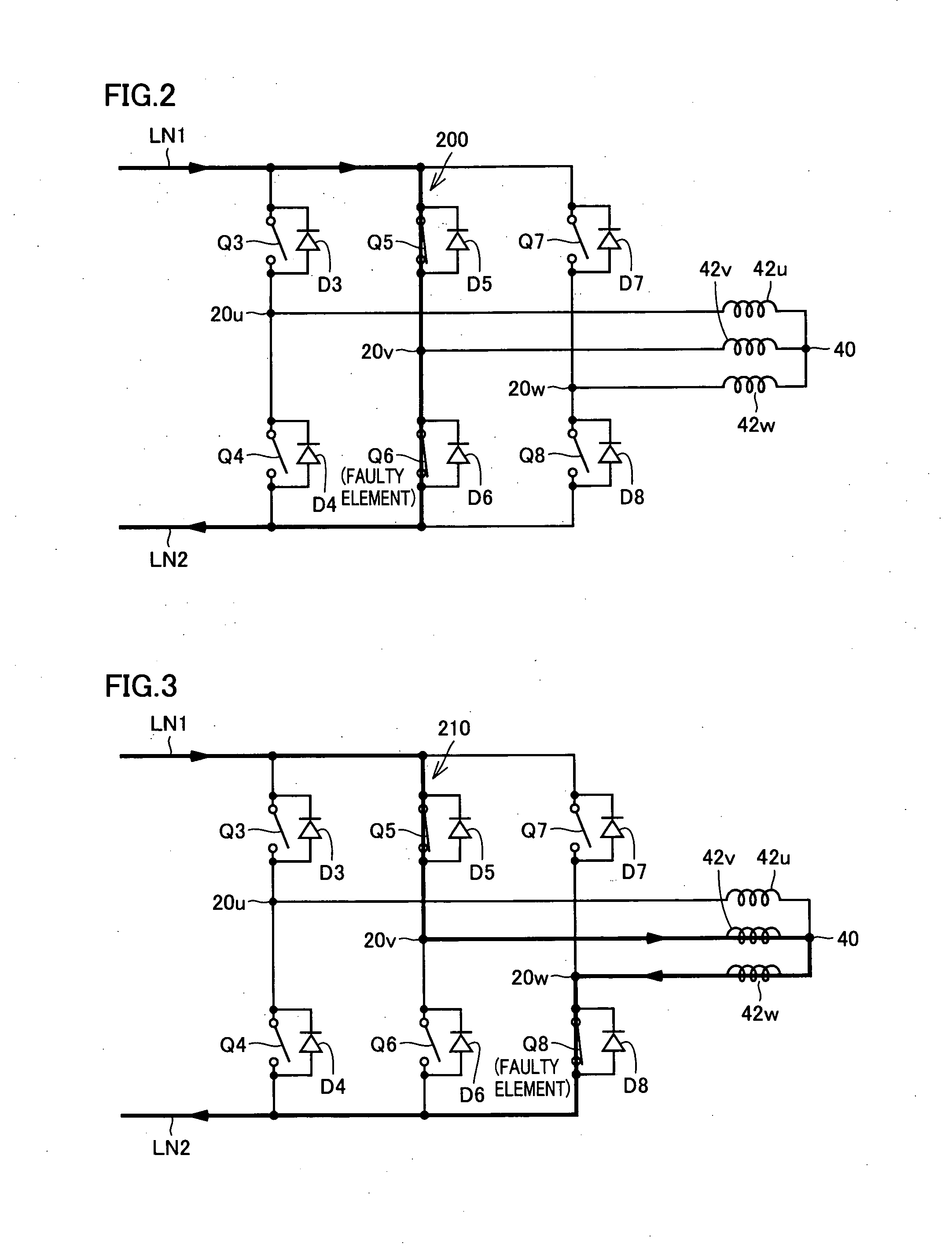
[0095]In the first and second embodiments of the invention, the switching pattern is set to turn on successively switching elements Q3-Q8 forming inverter 14, and determines the shorted faulty switching element based on the relationship between overcurrent detection signal OIH and the switching pattern.

[0096]According to this configuration, the faulty element can be accurately determined by successively turning on all switching elements Q3-Q8. However, the number of times of turning on the switching elements increases in proportion to the number of the elements. Therefore, the switching elements may be significantly damaged due to an excessively large short circuit current that flows every time the switching element is turned on. In particular, when the short circuit path is formed via the switching elements forming the upper and lower arms of the same phase (see FIG. 2), the short circuit current rapidly increases to promote the damage of the faulty element.

[0097]Accordingly, the t...


PUM


Abstract

Each of three-phase arm of an inverter has first and second switching elements connected in series together at a connection point to the corresponding phase coil of the three-phase motor. Control device turns on the first switching element of the i-th (i is a natural number smaller than four) for a predetermined time period, and determines that the second switching element of the i-th arm has a short fault, when an overcurrent exceeding a predetermined threshold is detected within the predetermined time period. The predetermined time period is shorter than a time period from a time point of turning on the first switching element of the i-th arm to a time point of attaining the predetermined threshold by a current flowing through a path extending from a power supply line through the second switching element of the remaining arm other than the i-th arm to a ground line.

Description

[0001]This nonprovisional application is based on Japanese Patent Application No. 2007-176068 filed on Jul. 4, 2007 with the Japan Patent Office, the entire contents of which are hereby incorporated by reference.BACKGROUND OF THE INVENTION[0002]1. Field of the Invention[0003]The present invention relates to an abnormality detecting device of an electric power converting device and an abnormality detecting method, and particularly to an abnormality detecting device for detecting a short circuit fault in a switching element forming an electric power converting device as well as an abnormality detecting method.[0004]2. Description of the Background Art[0005]In recent years, hybrid vehicles and electric vehicles have received attention as vehicles developed in view of environments. The hybrid vehicle uses, as a drive power source, a DC power supply, an inverter and an electric motor driven by the inverter in addition to a conventional engine. More specifically, the engine is driven to p...

Claims


Application Information

Patent Timeline
Patent Type & Authority Applications(United States)
IPC IPC(8): H02H9/02H02M7/48
CPCB60L3/0023G01R31/42H02P29/0241Y02T10/64
Inventor YAMADA, KENJI
Owner DENSO CORP
Why Eureka
Try Eureka