Novel stamping equipment used for motor processing

A stamping equipment and a new technology, applied in the field of stamping equipment for new motor processing, can solve the problems of unfavorable motor processing enterprises, such as saving production costs, high production costs, and complex structures, and achieve simple structure, low production costs, and simple transmission structure Effect

Pending Publication Date: 2017-06-13
SILVER DIAMOND ELECTRIC CO LTD TIANJIN
View PDF2 Cites 7 Cited by
  • Summary
  • Abstract
  • Description
  • Claims
  • Application Information

AI Technical Summary

Problems solved by technology

The structure of the existing stamping equipment for motor shells is relatively complicated, and the production cost is relatively high, which is not conducive to saving production costs for motor processing enterprises. Therefore, it is necessary to develop a stamping equipment for motor processing with a relatively simple structure and relatively low production costs.

Method used


Image

  • Novel stamping equipment used for motor processing

Examples


Embodiment

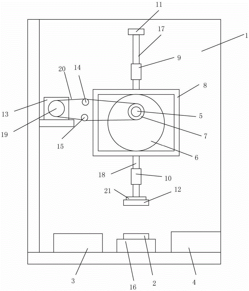
[0020] Such as figure 1 As shown, a new type of stamping equipment for motor processing includes a frame 1, a lower mold 2, a raw material tank 3, a receiving tank 4, a rotating rod 5, an eccentric wheel 6, a driven wheel 7, a frame body 8, and an upper fixing sleeve 9 , the lower fixed sleeve 10, the limit plate 11, the upper mold 12, the motor 13, the rising tensioner 14, the lower tensioner 15, the bottom of the frame 1 is equipped with a lower mold seat 16, and the lower mold 2 is installed on the lower mold seat 16 Above, the raw material chute 3 is installed on the frame 1 and it is located on one side of the lower mold 2, the receiving trough 4 is installed on the frame 1 and it is located on the other side of the lower mold 2, and the rotating rod 5 is installed on the frame 1 Above, the wheel shaft of the eccentric wheel 6 is installed on the rotating rod 5, the driven wheel 7 is installed on the rotating rod 5, the frame body 8 is arranged outside the eccentric wheel...


PUM


Abstract

The invention belongs to the field of motor processing equipment, and particularly relates to novel stamping equipment used for motor processing. The novel stamping equipment is characterized in that a rotating rod is mounted on a rack; a rotating shaft of an eccentric wheel is mounted on the rotating rod; a driven wheel is mounted on the rotating rod; a frame body is arranged outside the eccentric wheel; an upper upright rod is arranged at the upper end of the frame body; a lower upright rod is arranged at the lower end of the frame body; an upper fixed sleeve is mounted on the rack, and sleeves the outside of the upper upright rod; a lower fixed sleeve is mounted on the rack, and sleeves the outside of the lower upright rod; a limiting plate is positioned above the upper fixed sleeve, and is connected with the tail end of the upper upright rod; an upper mold is arranged between the lower fixed sleeve and a lower mold, and is connected with the tail end of the lower upright rod; the output shaft of a motor is connected with a driving wheel; the driving wheel and the driven wheel are driven through a belt; and an upper tensioning wheel and a lower tensioning wheel adhere to the belt.

Description

technical field [0001] The invention belongs to the field of motor processing equipment, and in particular relates to a novel stamping device for motor processing. Background technique [0002] Motor (English: Electric machinery, commonly known as "motor") refers to an electromagnetic device that realizes the conversion or transmission of electric energy according to the law of electromagnetic induction, and is represented by the letter M (the old standard uses D) in the circuit. Its main function is to generate driving torque as a power source for electrical appliances or various machinery. The generator is represented by the letter G in the circuit, and its main function is to convert electrical energy into mechanical energy. During the processing of the motor, the housing of the motor needs to be stamped and formed by stamping equipment. The structure of the existing stamping equipment for motor shells is relatively complicated, and the production cost is relatively hig...

Claims


Application Information

Patent Timeline
Patent Type & Authority Applications(China)
IPC IPC(8): H02K15/14
CPCH02K15/14
Inventor 郑波
Owner SILVER DIAMOND ELECTRIC CO LTD TIANJIN
Why Eureka
Try Eureka