
Ripple compensation circuit based on COT (constant on-time) mode buck converter

A technology of ripple compensation and converter, which is applied in the field of on-chip ripple compensation control circuit, can solve the problems of increasing the scope of application of the circuit, and achieve the effect of increasing the scope of application, increasing the accuracy and reducing the overall cost

Inactive Publication Date: 2017-06-13
UNIV OF ELECTRONICS SCI & TECH OF CHINA
View PDF3 Cites 7 Cited by
  • Summary
  • Abstract
  • Description
  • Claims
  • Application Information

AI Technical Summary

Problems solved by technology

[0005] The purpose of the present invention is to provide a ripple compensation control circuit for a DC-DC step-down converter in view of the stability problem brought by the current low ESR capacitor to the COT control system. Only one circuit module is used to reduce the conversion The overall cost of the device, while increasing the scope of application of the circuit

Method used


Image

  • Ripple compensation circuit based on COT (constant on-time) mode buck converter
  • Ripple compensation circuit based on COT (constant on-time) mode buck converter
  • Ripple compensation circuit based on COT (constant on-time) mode buck converter

Examples


Embodiment Construction

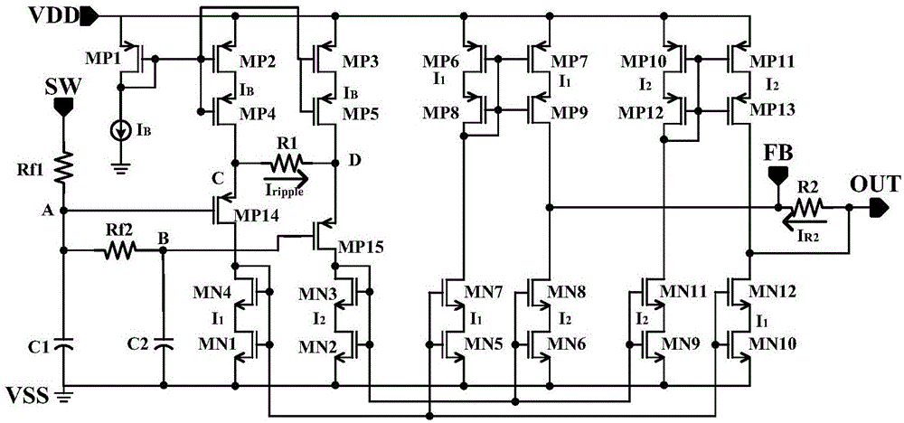
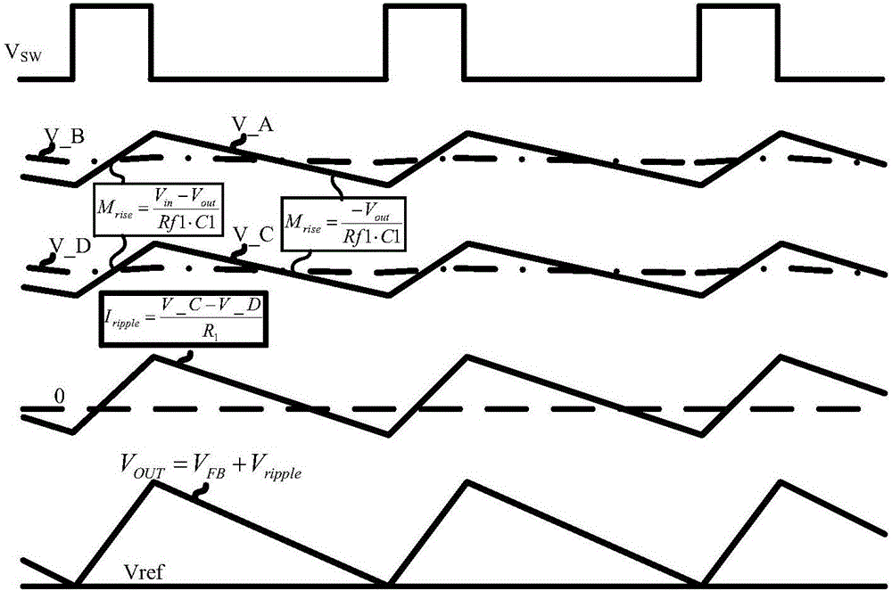
[0018] Such as figure 1 As shown, the present invention adopts an on-chip compensation technology, by processing the potential information at the switch node SW of the step-down converter to generate AC ripple information that is in phase with the inductor current, and the ripple compensation control circuit converts it to Superimposed on the feedback signal, so as to ensure that the output capacitor ripple with phase lag is weaker than the compensated ripple, and ensure the stable operation of the system; at the same time, it avoids the need for repeated design of the parameters of the traditional off-chip ripple compensation circuit in different applications. The scope of application of the circuit is increased.

[0019] The present invention will be described in detail below in conjunction with the accompanying drawings.

[0020] The concrete circuit schematic diagram of the present invention is as figure 1 As shown, it includes the first NMOS transistor MN1, the second N...


PUM


Abstract

The invention relates to a ripple compensation circuit based on a COT (constant on-time) mode buck converter, and belongs to the technical field of electronic circuits. The ripple compensation circuit has the advantages that by adopting a on-chip compensation technique, the potential information of a switch node SW of the buck converter is processed to produce alternating current ripple information being consistent with the inductive current in phase, and the alternating current ripple information is superposed to a feedback signal by a ripple compensation control circuit, so as to ensure that the output capacitive ripple with phase lag is weaker than the compensated ripple, and realize the stable working of the system; the problem of repeated design of parameters of the traditional off-chip ripple compensation circuit in different applications is solved, and the application range of the circuit is broadened.

Description

technical field [0001] The invention belongs to the technical field of electronic circuits, and in particular relates to an on-chip ripple compensation control circuit of a DC-DC step-down converter used for COT mode control. Background technique [0002] Compared with the traditional voltage-mode control or current-mode control, the control system based on output ripple has the characteristics of faster transient response and simple control loop, especially the ripple control based on constant on-time due to Its potential in adaptive constant frequency characteristics has attracted much attention. However, the capacitive characteristics of the output capacitor lead to a certain phase lag characteristic of the output voltage relative to the current information, so for all converter systems that directly use the output ripple for control, the equivalent series resistance ESR of the sufficient output capacitor is the system conditions necessary for stability. This requires t...

Claims


Application Information

Patent Timeline
Patent Type & Authority Applications(China)
IPC IPC(8): H02M1/14
CPCH02M1/143
Inventor 明鑫魏秀凌高笛赵佳祎唐韵扬张宣辛杨立王卓张波
Owner UNIV OF ELECTRONICS SCI & TECH OF CHINA
Learn More