Vibrating diaphragm-type zero-frequency and high-tone-quality loudspeaker

A zero-frequency, loudspeaker technology, applied in the field of audio equipment, can solve problems such as difficult to guarantee sound quality and poor low-frequency response of loudspeakers, and achieve the effect of simple structure, low distortion, and small volume

Inactive Publication Date: 2017-06-13
方炳钧
View PDF7 Cites 0 Cited by
  • Summary
  • Abstract
  • Description
  • Claims
  • Application Information

AI Technical Summary

Problems solved by technology

[0007] The purpose of the present invention is to provide a diaphragm-type zero-frequency high-quality sound speaker in order to solve the disadvantages of poor low-frequency response and difficult sound quality effect of existing speakers.

Method used


Image

  • Vibrating diaphragm-type zero-frequency and high-tone-quality loudspeaker
  • Vibrating diaphragm-type zero-frequency and high-tone-quality loudspeaker

Examples


Embodiment 1

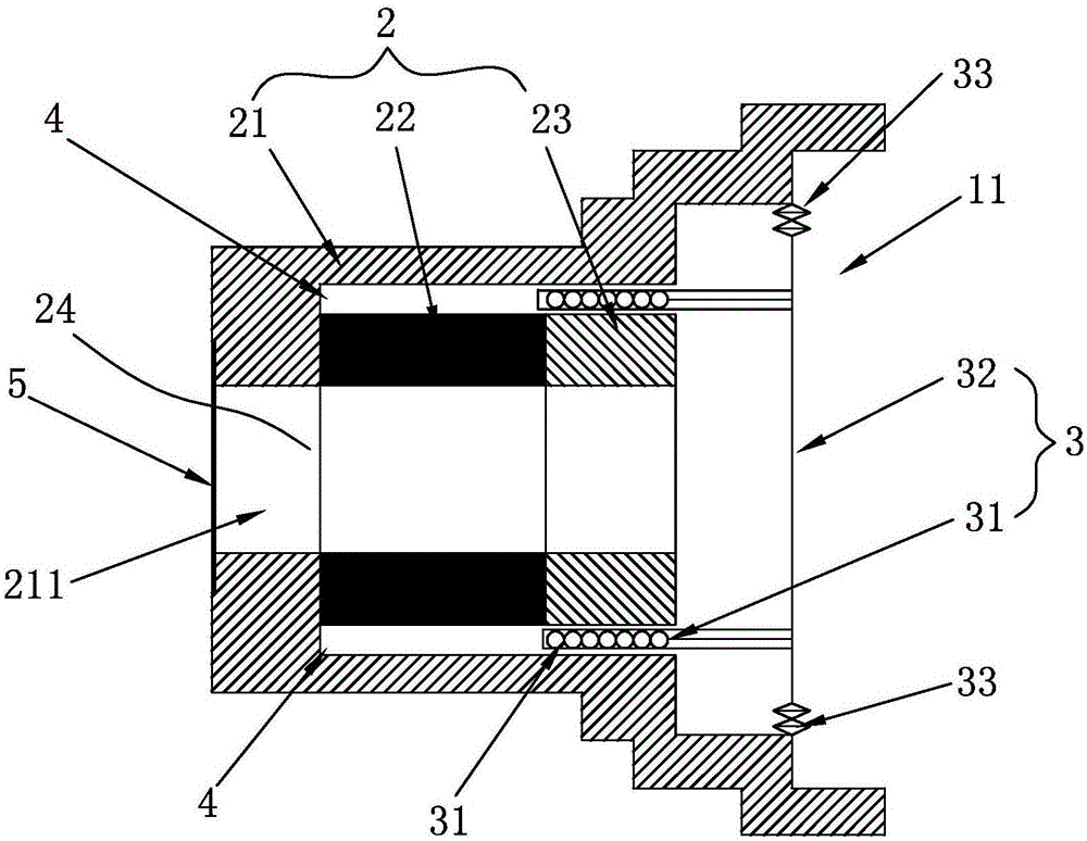
[0026] refer to figure 1 The diaphragm-type zero-frequency high-quality sound speaker is composed of a magnetic field part 2 and a diaphragm moving part 3. The magnetic field part 2 is a hollow body composed of an annular iron block 21, a magnetic ring 22 and a washer 23. The annular iron block 21 described above is a barrel-shaped iron block. A through hole 211 is provided in the middle of the bottom of the annular iron block 21. The magnetic ring 22 and the washer 23 are arranged in sequence and fixed on the inner bottom of the annular iron block 21. The magnetic ring 21 There is a gap 4 between the outer wall of the ring 22 and Washer 23 and the inner wall of the annular iron block 21; the diaphragm moving part 3 is composed of a voice coil 31, a diaphragm 32 and an elastic wave 33, and the voice coil 31 is wound The coil in the gap 4, the diaphragm 32 is fixedly installed at the opening 11 of the annular iron block 21, and is a film that is tightly attached to the voice co...

Embodiment 2

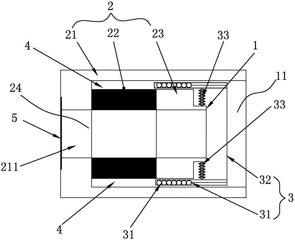
[0032] refer to figure 2 As shown, the technical characteristics of the present invention are: the inner side of the washer 23 is provided with an annular raised portion 1, the inner side of the elastic wave 33 is fixed with the annular raised portion 1, and the outer side is fixed on the voice coil 31; The diaphragm 32 is fixed on the voice coil 31 through the outer edge. All the other are the same as the above embodiment.

[0033] According to the above technical characteristics, the technical characteristics and structure of the present invention (hereinafter referred to as "diaphragm type loudspeaker") and the existing "paper cone type loudspeaker" are as follows:

[0034] 1. The difference in performance and characteristics between the two is:

[0035] 1. "Paper cone type speaker" has a paper cone, and "diaphragm type speaker" has a diaphragm.

[0036] 2. "Paper cone type speaker" relies on the paper cone to convert the movement of the voice coil into sound, and "diap...


PUM


Abstract

The invention relates to a vibrating diaphragm-type zero-frequency and high-tone-quality loudspeaker which comprises a magnetic field component and a vibrating diaphragm moving component, wherein the magnetic field component is a hollow body formed by an annular iron block, a magnet ring and a washer; the annular iron block is an iron block of a barrel-shaped structure; a through hole is formed in the middle position of the bottom of the annular iron block; the magnet ring and the washer are sequentially arranged and fixed at the bottom in the annular iron block; a gap is reserved between the outer walls of the magnet ring and the washer and the inner wall of the annular iron block; the vibrating diaphragm moving component comprises a voice coil, a vibrating diaphragm and a damper; the voice coil is a coil wound in the gap; the vibrating diaphragm is a thin film which is fixedly arranged in an opening of the annular iron block and clung to the voice coil; the thin film compresses air to make a sound when the voice coil cuts a magnetic line generated by the magnet ring; and the damper is arranged at the inner side of the vibrating diaphragm and is located in the opening of the annular iron block. The vibrating diaphragm-type zero-frequency and high-tone-quality loudspeaker has the advantages of being low in distortion, sonorous in sound, low in volume, simple in structure and low in cost.

Description

technical field [0001] The invention relates to an audio device, in particular to a loudspeaker. Background technique [0002] The audio system consists of three major components, one is the sound source; the other is the power amplifier; the third is the speaker that completes the electroacoustic conversion. The audio industry has developed to the present, and speakers are the bottleneck for the further development of audio. [0003] Comparing power amplifiers and speakers, the electro-acoustic indicators of the two are very different: the distortion of the power amplifier can currently reach 0.1% or even 0.01%, and its low-end frequency response can be lower than 20 weeks of the lower limit of the audio frequency, tending to zero frequency. The distortion of the speaker is always hovering between 3 and 5%, especially its low-end frequency response is difficult to reach below 100 cycles, which is far from the 20 cycles of the lower limit of the audio frequency, let alone r...

Claims


Application Information

Patent Timeline
Patent Type & Authority Applications(China)
IPC IPC(8): H04R9/06H04R9/02
CPCH04R9/02H04R9/06H04R2400/11
Inventor 方炳钧
Owner 方炳钧
Why Eureka
Try Eureka