Tool for welding slab fan shape bevel frame and welding method thereof

A fan-shaped section and beveled edge technology, which is applied in welding equipment, auxiliary welding equipment, welding/cutting auxiliary equipment, etc., can solve the problems of easy deformation due to shrinkage, oil holes can not pass through, and large welding volume, etc., to increase profits and save manufacturing The effect of cost and simple structure

Inactive Publication Date: 2017-06-16
TIANJIN SERI MACHINERY EQUIP
View PDF0 Cites 1 Cited by
  • Summary
  • Abstract
  • Description
  • Claims
  • Application Information

AI Technical Summary

Problems solved by technology

[0002] It is the first time that our company undertook the project of the sector section of the SMS panel billet. One of the bottom frames is welded by six large ribs, small pieces, bottom plate and small ribs. The large ribs on both sides are sloped. This frame All welding adopts full-penetration welds, and the welding volume is large, and the shrinkage is easy to deform after welding. There are long oil holes connected to the roller seat on the hypotenuse plate. Considering the feasibility of processing, the single Drill out the long oil hole, and then weld the small block on the oil hole to fit the roller seat, and then weld it with other parts to form a frame. During machining, drill on the small block and slant plate according to the dimensional tolerance in the drawing. The holes connected to the oil hole and the joint hole, due to the strict dimensional tolerance, the shrinkage deformation during welding and the angle error of the hypotenuse will cause the hole on the small block to fail to communicate with the oil hole on the inclined plate
[0003] When faced with this situation, if you want to solve this problem, the main problem is to solve the problem of welding shrinkage deformation and bevel angle. How to solve the problem of welding shrinkage deformation and bevel angle? By increasing welding shrinkage The amount can only solve the problem of welding shrinkage and deformation, but it cannot guarantee the angle of the hypotenuse, and it will also cause the holes on the small block and the oil holes on the inclined plate to be unable to communicate.

Method used


Image

  • Tool for welding slab fan shape bevel frame and welding method thereof
  • Tool for welding slab fan shape bevel frame and welding method thereof
  • Tool for welding slab fan shape bevel frame and welding method thereof

Examples


Embodiment Construction

[0020] In order to further understand the invention content, characteristics and effects of the present invention, the following examples are given, and detailed descriptions are as follows in conjunction with the accompanying drawings:

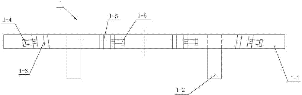
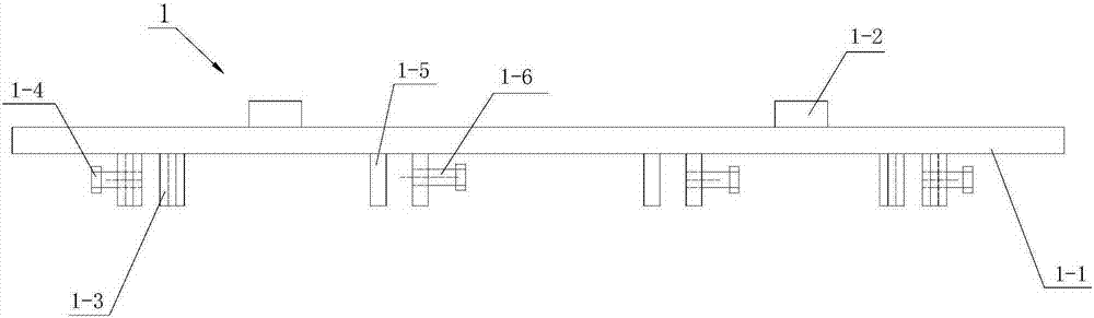
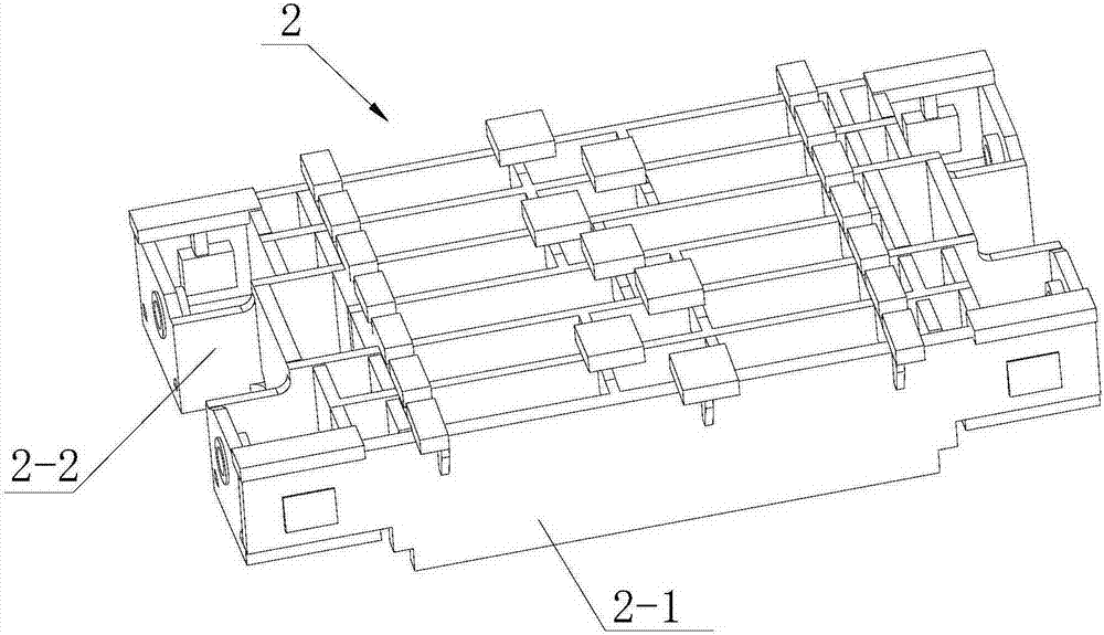
[0021] see Figure 1 to Figure 4 , a tooling for welding a hypotenuse frame of a slab segment, including two sets of welding positioning support assemblies 1 with the same structure, the welding positioning support assembly 1 includes a support beam 1-1, and the outer side of the support beam is welded with a support Leg 1-2, the bottom surface of the supporting leg is the first reference plane; the inner side of the support beam is provided with the inclined rib plate consistent with the slope of the inclined rib plate 2-1 on both sides of the hypotenuse frame 2 of the slab sector Positioning groove plate 1-3, the first tightening bolt 1-4 is provided on one side of each inclined rib plate positioning groove; the inner side of the support be...


PUM


Abstract

The invention relates to a tooling for welding a hypotenuse frame of a slab segment and a welding method thereof, comprising two sets of welding positioning support assemblies with the same structure, including a support beam, and support legs are welded on the outside of the support beam; The inner side is provided with inclined rib plate positioning grooves consistent with the slope of the inclined rib plates on both sides of the hypotenuse frame of the slab sector, and a first tightening bolt is provided on one side of each inclined rib plate positioning groove; The inner side of the support beam between the locating grooves of the ribs is also provided with the vertical rib locating slots corresponding to the two vertical ribs in the middle of the hypotenuse frame of the slab sector, and each vertical rib locating slot is provided with There is a second jacking bolt, and a welding shrinkage compensating gasket is also equipped in the positioning groove of the above-mentioned inclined rib plate and the positioning groove of the vertical rib plate. Using the above-mentioned tooling method, the deformation caused by welding shrinkage is effectively prevented, and at the same time, the inclination of the ribs on both sides of the workpiece is ensured. It is qualified once during machining, which saves a lot of rework time and rework cost.

Description

technical field [0001] The invention belongs to the technical field of machining, and in particular relates to a frock for welding hypotenuse frames of slab sectors and a welding method thereof. Background technique [0002] It is the first time that our company undertook the project of the sector section of the SMS panel billet. One of the bottom frames is welded by six large ribs, small pieces, bottom plate and small ribs. The large ribs on both sides are sloped. This frame All welding adopts full-penetration welds, and the welding volume is large, and the shrinkage is easy to deform after welding. There are long oil holes connected to the roller seat on the hypotenuse plate. Considering the feasibility of processing, the single Drill out the long oil hole, and then weld the small block on the oil hole to fit the roller seat, and then weld it with other parts to form a frame. During machining, drill on the small block and slant plate according to the dimensional tolerance ...

Claims


Application Information

Patent Timeline
IPC IPC(8): B23K37/04B23K37/00
CPCB23K37/0443B23K37/00B23K2101/24
Inventor 张冲李鹤唐郡东
Owner TIANJIN SERI MACHINERY EQUIP
Why Eureka
Try Eureka