

Cup-shaped part reverse extrusion molding device and method
A technology for back extrusion and cup-shaped parts, which is applied in the direction of metal extrusion, metal extrusion dies, containers to be extruded metal, etc., can solve the problems of reducing the hot back extrusion forming force of cup-shaped parts and low production efficiency. , to achieve considerable economic benefits, improve service life, and reduce the effect of extrusion cracks.
- Summary
- Abstract
- Description
- Claims
- Application Information
AI Technical Summary
Problems solved by technology
Method used
Image

Examples
Embodiment
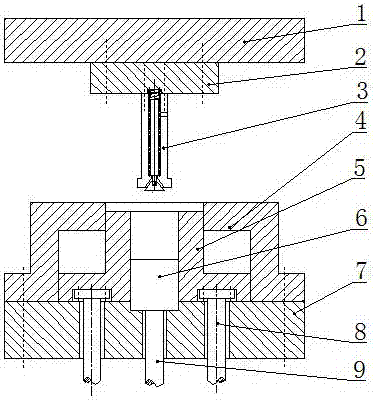
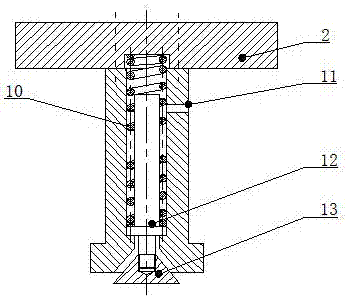
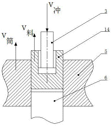
[0053] Such as Figure 1-8 As shown, a cup-shaped part reverse extrusion forming device includes an upper template 1, a backing plate 2, a reverse extrusion punch 3, a compression spring 10, a limit sleeve 4, a reverse extrusion cylinder 5, a top block 6, Ejector rod 9, hydraulic cylinder pull rod 8, lower template 7; backing plate 2 is provided under the upper template 1, reverse extrusion punch 3 is connected under the backing plate 2, reverse extrusion cylinder 5 is arranged inside the limit sleeve 4, and reverse extrusion A top block 6 is arranged inside the extrusion cylinder 5, and the bottom of the top block 6 is a push rod 9, and a hydraulic cylinder tie rod 8 is fixed between the reverse extrusion cylinder 5 and the lower template 7;
[0054] The reverse extrusion punch 3 is a two-stage stepped cylindrical structure, the upper part is a small cylinder and the lower part is a large cylinder; the inside of the punch is provided with a through hole, which is divided into...
PUM
 Abstract
Description
Claims
Application Information